
28V DC To 5V DC Switch-Mode Converter (Regulator)
The 28VDC to 5VDC switching converter circuit operates by converting a higher voltage direct current (DC) input into a lower voltage DC output with increased efficiency. The circuit typically employs a power switch, usually a transistor, which rapidly turns on and off to control the energy transfer from the input to the output. This switching action allows the circuit to maintain a stable output voltage while minimizing energy loss, a significant advantage over linear regulators which dissipate excess voltage as heat.
Key components of the circuit include an inductor, a diode, and capacitors. The inductor stores energy when the switch is closed and releases it to the output when the switch is open. The diode prevents backflow of current and ensures that the energy flows in the correct direction. Input and output capacitors are used to smooth out voltage fluctuations, providing a stable output voltage.
The efficiency of this switching converter can be further enhanced by employing techniques such as pulse-width modulation (PWM) to control the duty cycle of the switch, optimizing the energy transfer process. Additionally, feedback mechanisms may be implemented to monitor the output voltage and adjust the switching operation accordingly, ensuring consistent performance under varying load conditions.
Overall, this 28VDC to 5VDC switching converter circuit is an effective solution for applications requiring efficient power conversion, making it suitable for powering low-voltage devices from higher voltage sources.This is a 28VDC to 5VDC switching converter circuit. As a switch-mode voltage regulator, this circuit gives higher efficiency than linear regulator type.. 🔗 External reference
Related Circuits
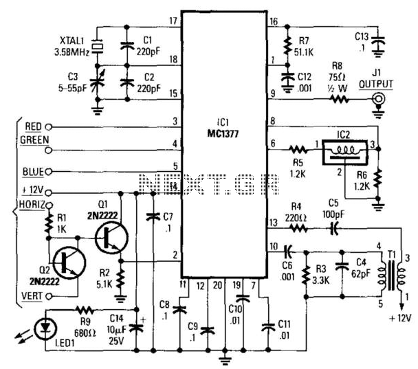
This circuit utilizes a Motorola MC1377 to generate NTSC video from an RGB source. The components are not critical, with the exception of resistor R7, which should have a tolerance of 1%, and capacitor CB, which should have a...
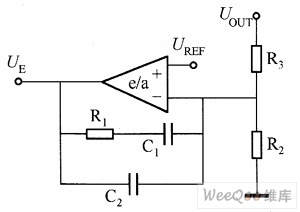
The on-off type DC/DC converter operates in two modes. One mode maintains a constant duty cycle for the switch, while the other varies the pulse frequency modulation (PFM) while keeping the on-time constant. The pulse width modulation (PWM) DC/DC...
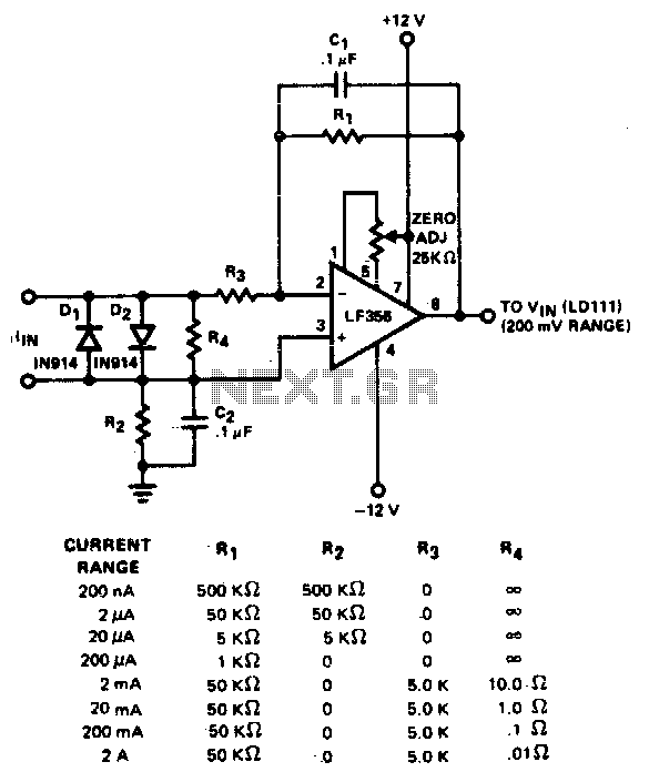
The converter features eight decades of current range. The circuit is intended to be used with the 200 mV range of a DVM. The described converter circuit is designed to accommodate a wide range of current measurements, spanning eight decades....
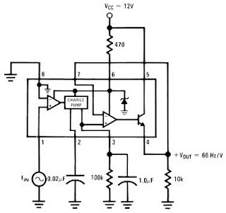
The LM2917 IC chip is specifically designed as a Frequency to Voltage Converter. It requires only a few external components for its operation. The datasheet for the LM2917 IC includes several application examples of the Frequency to Voltage Converter....
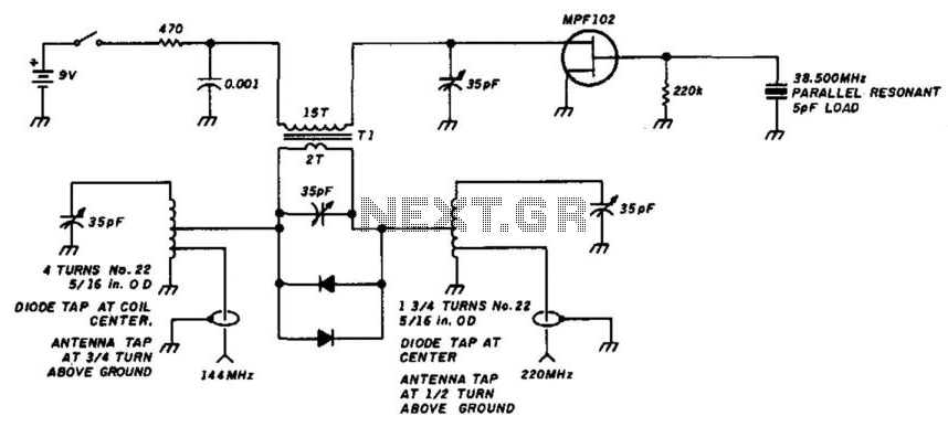
A simple circuit utilizing a single transistor converts 220 MHz to 144 MHz or vice versa, as the mixer is bilateral. The transformer has 15 turns on the primary and 2 turns on the secondary (#24 AWG wire) on...
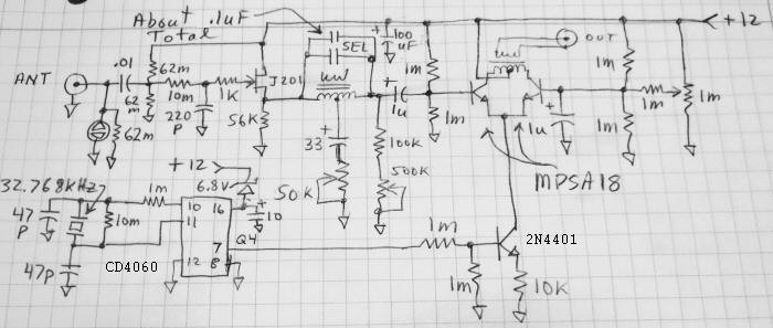
Using a circuit similar to the LF block converter, a Schumann Resonance Converter has been developed to shift near-DC signals up to approximately 2 kHz for compatibility with a standard soundcard. The initial test results indicate successful operation, with...