
Rgb/Ntsc Converter
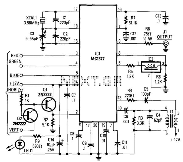
The circuit employs the Motorola MC1377 integrated circuit, which is designed specifically for video signal processing. It converts RGB signals, typically used in computer graphics and high-quality displays, into the NTSC format suitable for standard television broadcasts. The MC1377 achieves this by taking the three separate color signals (Red, Green, and Blue) and combining them into a composite video signal.
Resistor R7 plays a crucial role in setting the gain of the circuit. Its 1% tolerance ensures that the gain remains consistent, which is important for maintaining video quality and preventing distortion. A variation in this resistor's value could lead to significant differences in output brightness and color accuracy.
Capacitor CB, with a tolerance of 2%, is likely involved in filtering or coupling within the circuit. The tolerance level is important as it affects the frequency response and stability of the video signal. A capacitor with too high a tolerance could introduce unwanted noise or signal degradation, impacting the overall performance of the video output.
In summary, this circuit design effectively transforms RGB signals into an NTSC video format, ensuring high fidelity in color reproduction and signal integrity through careful selection of component tolerances. Using a Motorola MC1377, this circuit produces NTSC video from an RGB source. Components are not critical, except for R7 and CB, which should be 1% and 2% tolerance, respectively. 🔗 External reference
Related Circuits
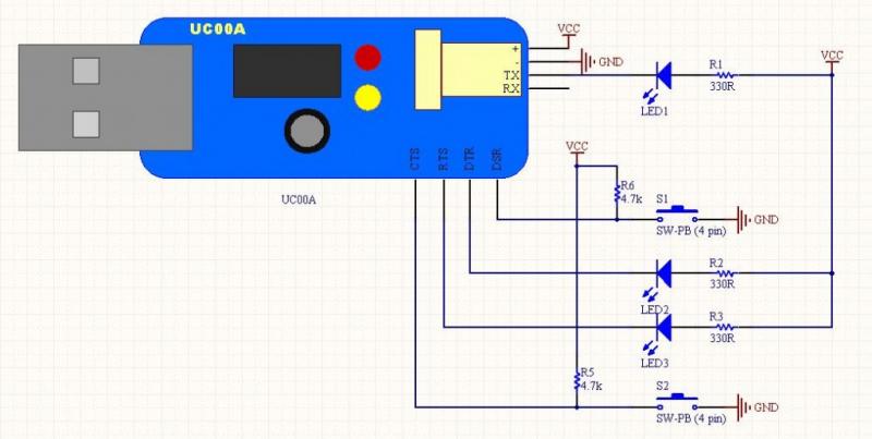
The LEDs operate in an active-low configuration (0), while the initial state of the switches is high (1). In other words, the PC software must send a low signal (0) to activate the LEDs, and if a low signal...
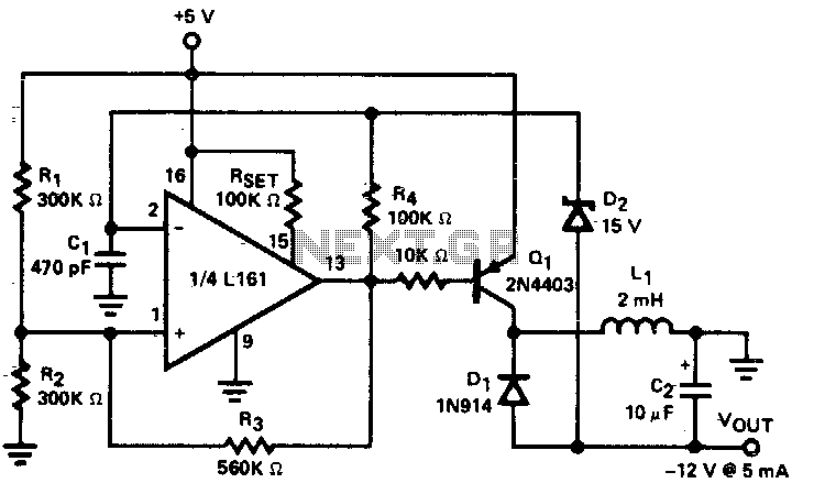
A low power DC to DC converter is created by integrating a flyback circuit with a square wave oscillator. The operating frequency is set at 20 kHz to reduce the size of the inductor (L1) and capacitor (C2). Regulation...
The simplest current-to-voltage (I to V) converter is a basic resistor. However, the disadvantage of this simple configuration is that it presents a nonzero impedance to the input current source. The I to V converter is an essential circuit in...
A high voltage step-up DC power supply using adjustable flyback conversion. The described circuit is a high voltage step-up DC power supply that employs an adjustable flyback converter topology. Flyback converters are widely used in applications requiring electrical isolation and...
A closed-loop or servo system has the capability to stabilize the controlled plant at a specified operating condition. The plant, which is the controlled sub-system, can be... A closed-loop control system, commonly referred to as a servo system, is designed...

An analog-to-digital converter (ADC) transforms an analog input voltage into a digital value. This circuit illustrates the operation of an ADC, utilizing the ATmega8 microcontroller to control its functionality. The resolution of the converter denotes the number of discrete...