
2N3055 Variable Power Supply
This variable power supply circuit is designed to provide a versatile and adjustable output voltage, suitable for various electronic applications. The circuit typically utilizes a linear voltage regulator, such as the LM317, which is capable of outputting a range of voltages from 1.5 V to 15 V.
The design includes a few key components: a transformer to step down the AC mains voltage, a bridge rectifier to convert AC to DC, and filter capacitors to smooth the rectified voltage. The adjustable output is achieved by connecting a pair of resistors to the voltage regulator, which sets the output voltage according to the desired level based on the formula provided in the regulator's datasheet.
To ensure stable operation, a heat sink may be added to the voltage regulator, especially when the circuit operates at higher output currents. The maximum output current of 500 mA indicates that the circuit can power small to medium-sized loads, making it suitable for testing and powering various electronic devices.
Safety features, such as fuses or circuit breakers, can be integrated into the design to protect against overcurrent conditions. Additionally, proper decoupling capacitors should be placed close to the output to filter out any high-frequency noise, ensuring a clean power supply for sensitive components.
Overall, this simple variable power supply circuit is an effective solution for providing adjustable voltage levels with minimal cost and complexity, making it an ideal choice for hobbyists and professionals alike.This simple variable power supply circuit has a low production cost and delivers an output voltage between 1,5 V and 15 V with a 500 mA maximum current. It.. 🔗 External reference
Related Circuits
A 100W RF power amplifier circuit is constructed using two BLY94 transistors. For additional RF amplifier options, refer to the list below. Components include active components. The 100W RF power amplifier circuit utilizing BLY94 transistors is designed to amplify radio...
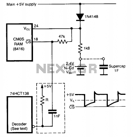
To prevent data loss when a CMOS RAM transitions from normal operation (Vcc = 5 volts) to standby mode (Vcc = VBAT), it is crucial to maintain the CS pin close to the Vcc rail at all times. This...
This dual polarity power supply is easy to build, requires few parts, and is adjustable from 0-15 volts. It is great for powering op amp circuits, as well as other circuits that require a dual supply voltage. The dual polarity...
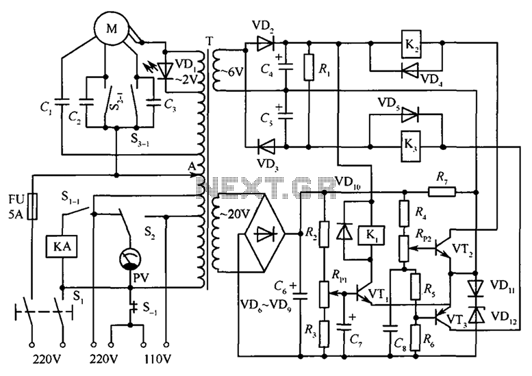
The circuit illustrated in the figure features an automatic voltage regulator (T) that utilizes a servo motor to ensure a constant output voltage. The transistors used are VT1 and VT2 (3DK9C, with a range of 65 to 85) and...
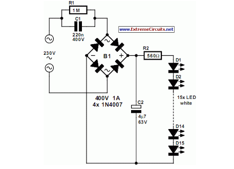
An array of white LEDs can serve as an effective small lamp for the living room. LED lamps are commercially available. LED arrays are increasingly popular for providing ambient lighting in residential spaces. The use of white LEDs in a...
The following circuit illustrates a Power Amplifier Circuit Diagram utilizing a 2N3055 transistor. Features include a 500-ohm current and an optimal voltage of 50V. The power amplifier circuit based on the 2N3055 transistor is designed to deliver significant output power,...