
Power AmplifierCircuit With 2N3055 Transistor
The power amplifier circuit based on the 2N3055 transistor is designed to deliver significant output power, making it suitable for applications in audio amplification and other high-power scenarios. The 2N3055 is a widely used NPN power transistor known for its robustness and ability to handle high currents, typically up to 15A, and voltages of 60V.
In this circuit, the transistor is configured in a common emitter arrangement, which provides voltage gain and is commonly employed in amplifier designs. The input signal is fed into the base of the transistor through a coupling capacitor, which blocks any DC offset and allows only the AC component of the signal to pass through. The biasing resistors are crucial as they set the operating point of the transistor, ensuring it remains in the active region for linear amplification.
The output stage of the circuit typically includes a load resistor connected to the collector of the 2N3055, allowing the amplified signal to drive speakers or other devices. The emitter may have a resistor for stability and to provide feedback, which can help linearize the output and improve performance.
Power supply considerations are also essential; the circuit requires a well-regulated DC supply, capable of providing the necessary current and voltage levels, ideally around 50V for optimal performance. Proper heat sinking for the 2N3055 is critical, as it can generate significant heat during operation, which could lead to thermal runaway if not adequately managed.
Overall, this power amplifier circuit is a reliable solution for boosting audio signals, with the 2N3055 transistor providing a balance of performance and durability for various applications.The following circuit shows about Power Amplifier Circuit Diagram. This circuit using 2N3055 Transistor.Features: 500ohm current, 50V optimal .. 🔗 External reference
Related Circuits
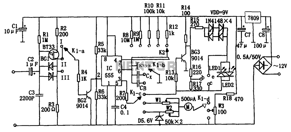
The frequency detection circuit utilizes a transistor line, adjustable via a preset switch K1, to convert capacitance and frequency measurements. The K1 switch is positioned to detect capacitance. The circuit comprises components including a 555 timer, resistors R8 to...
This chapter provides detailed schematics of various power supplies suitable for use with common Ar/Kr ion tubes available to hobbyists in the surplus market. Included are examples of commercial designs (Omnichrome 150R and 532 head, Lexel 88 and head)...
The 567 IC tone decoder/detector can be utilized to construct a remote control or intercom system. This circuit is capable of controlling a relay or transmitting an audio signal. The 567 IC is a versatile component often employed in tone...
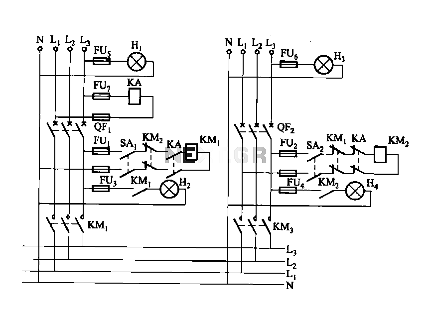
Dual power automatic recovery means one power supply and one standby power supply. When the main power supply is turned off, the standby power supply is automatically activated. Once the main power supply is restored, the system automatically exits...
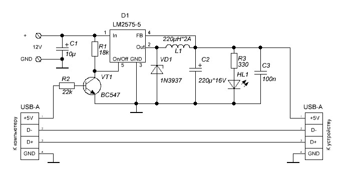
Additional power supply for USB devices. Refer to the page for an explanation of the related circuit diagram. The additional power supply for USB devices is designed to enhance the power availability for devices that may require more current than...
A typical circuit for welding equipment is illustrated in the following circuit diagram. The turn-on delay can be accurately controlled with Potentiometer P2, allowing for effective discharge management. The welding equipment circuit typically incorporates several key components to ensure proper...