
3.3V and 5V dual tracking regulator using LT3692 DC converter

The LT3692 is a highly efficient dual-output DC-DC converter designed for applications requiring both 3.3V and 5V outputs. This integrated circuit can provide a regulated output voltage while maintaining a low quiescent current, making it suitable for battery-powered devices. The device features a dual tracking capability, allowing both outputs to maintain a constant voltage relationship, which is essential for systems where load regulation and voltage accuracy are critical.
In the schematic, the LT3692 is typically connected to an input voltage source, which can range from 4.5V to 36V. The circuit design includes input capacitors to filter the input voltage and ensure stable operation. Output capacitors are also included to reduce voltage ripple and improve transient response.
The feedback pins of the LT3692 are connected to voltage divider networks, which set the output voltages to 3.3V and 5V, respectively. Additionally, compensation components may be added to optimize the control loop stability, ensuring reliable operation across varying load conditions.
Inductors are chosen based on the desired output current and efficiency requirements, while Schottky diodes may be used in the output stage to minimize voltage drop and improve efficiency. The layout of the PCB should be carefully designed to minimize parasitic inductance and capacitance, which can impact the performance of the converter.
This project is ideal for engineers looking to implement a compact, efficient power solution in their designs, providing stable power for microcontrollers, sensors, and other electronic components that require dual voltage levels.3.3V and 5V DC DC converter circuit design electronic project using LT3692 DC converter dual tracking regulator 🔗 External reference
Related Circuits
This project provides a simple temperature-controlled fan. If the difference between the actual temperature and the user-defined temperature is significant, the fan will operate. The temperature-controlled fan circuit utilizes a temperature sensor, a microcontroller, and a fan motor to regulate...
This is a simple circuit of a DC to DC converter utilizing the LM317T integrated circuit (IC). The LM317 is a well-known IC that comes in a TO-220 package. This high-performance IC features an input voltage range of 3...
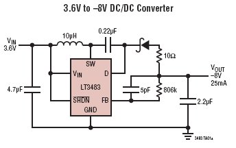
The LT3483/LT3483A are micropower inverting DC/DC converters featuring integrated Schottky diodes and a single resistor feedback mechanism. Their compact package size, high integration level, and the use of small surface mount components allow for a solution size as small...
The advanced credit card, referred to as the "microcontroller super card," incorporates numerous innovative enhancements. The initial step involved verifying the code and subsequently uploading it to the Arduino board. The developed code enabled a counter to increment from...
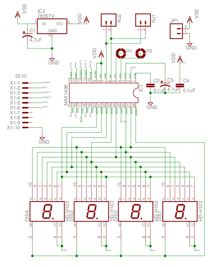
The MAX1496 is an analog-to-digital converter (ADC) that incorporates LED drivers, allowing for the construction of a 3 1/2 digit voltmeter using a minimal number of components. This device features both external and internal voltage reference options, along with...
This circuit diagram illustrates a triangular wave generating circuit utilizing a pair of operational amplifiers (Op-Amps). The LM741 Op-Amp is recommended for this application. The first Op-Amp, located on the left, functions as a comparator, while the second Op-Amp...