
Temperature controlled fan using microcontroller

The temperature-controlled fan circuit utilizes a temperature sensor, a microcontroller, and a fan motor to regulate airflow based on ambient temperature conditions. The primary components of the circuit include:
1. **Temperature Sensor**: A thermistor or a digital temperature sensor (such as the LM35 or DS18B20) is employed to measure the current ambient temperature. The sensor outputs a voltage or digital signal that corresponds to the temperature reading.
2. **Microcontroller**: A microcontroller, such as an Arduino or PIC, processes the temperature data from the sensor. It compares the measured temperature to a user-defined threshold value. If the difference exceeds a predetermined limit, the microcontroller activates the fan.
3. **Fan Motor**: A DC fan or an AC fan is controlled by the microcontroller using a relay or a transistor switch. The fan operates at varying speeds depending on the temperature difference. For example, a larger temperature difference may result in the fan running at full speed, while a smaller difference could cause it to run at a lower speed or remain off.
4. **User Interface**: A simple user interface, such as a potentiometer or buttons, allows the user to set the desired temperature threshold. An LCD display or LED indicators may be used to show the current temperature and the status of the fan.
5. **Power Supply**: The circuit requires an appropriate power supply to operate the microcontroller and the fan. This could be a battery or an AC adapter, depending on the fan type and the circuit design.
The schematic diagram would show the connections between the temperature sensor, microcontroller, fan motor, and user interface components. Proper consideration should be given to component ratings, power requirements, and safety features, such as fuses or thermal cutoffs, to ensure reliable operation of the temperature-controlled fan system.This project gives you a simple temperature controlled fan. If the difference between real temperature and the user temperature is high then the fan will run at. 🔗 External reference
Related Circuits
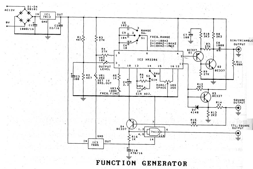
The signal generator, also known as "The Function Generator," is a device designed for use in a single machine. It is often associated with a significant cost. The function generator is a versatile electronic instrument used to generate various types...
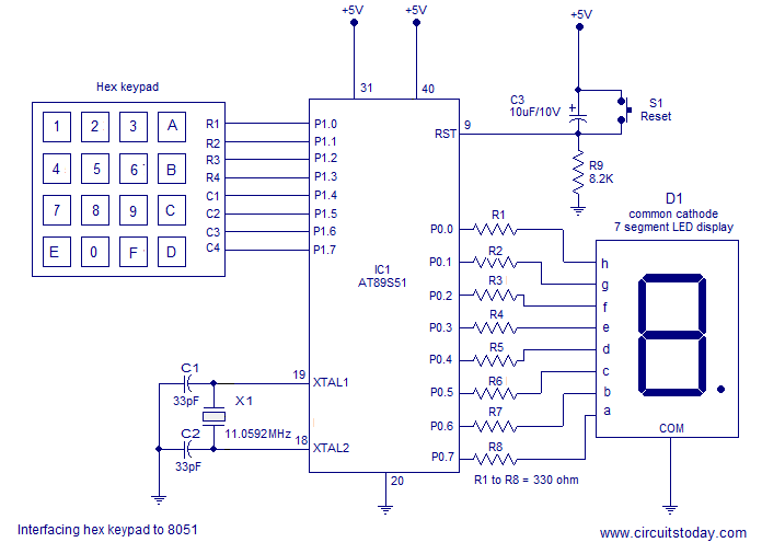
Interfacing a hex keypad to an 8051 microcontroller. The AT89S51 is utilized in this setup. A circuit diagram and assembly language program are included. A testing video is also provided. The interfacing of a hex keypad with the AT89S51 microcontroller...
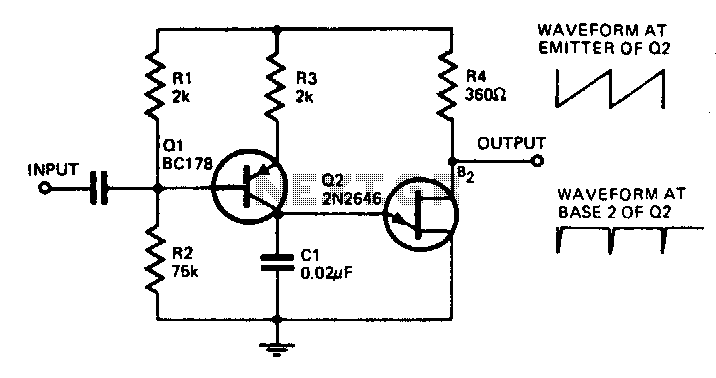
With the component values shown, the oscillator has a frequency of 8 kHz. When an input signal is applied to the base of Q1, the current flowing through Q1 is varied, thus affecting the time required to charge C1....
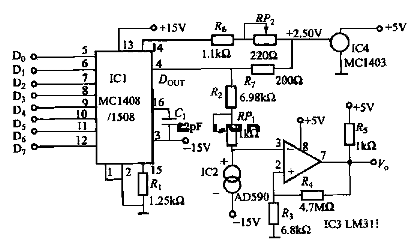
An 8 NC temperature adjusting circuit is presented, primarily composed of a D/A converter, a reference power supply, amplification components, temperature sensors, and other necessary elements. This circuit regulates the temperature within a range of 0-51°C and is suitable...
A clock-controlled relay, also known as a time delay relay, allows for the automatic activation of a load, such as a water pump, at a predetermined time. This device utilizes a standard clock mechanism to trigger the circuit, enabling...

This is a versatile Low-Frequency Oscillator (LFO) designed for various modulation applications. The frequency of the LFO can be controlled by voltage, enhancing the range of sound possibilities. The pulse width of the rectangular wave can be adjusted between...