
3 channel audio mixer (2N3904)
The described circuit functions as an audio mixer, designed to maintain a unity gain of one, ensuring that the output signal level matches the input signal level without amplification or attenuation. Each input channel is equipped with a 0.1 µF capacitor and a 100 kΩ resistor. The capacitor serves to block any DC offset in the audio signals, allowing only the AC audio signal to pass through to the subsequent stages of the mixer. The resistor, in conjunction with the capacitor, sets the output impedance of each input channel to 100 kΩ, which is a common impedance value that helps ensure compatibility with various audio equipment.
To accommodate multiple input channels, additional input paths can be created by replicating the existing configuration of one 0.1 µF capacitor and one 100 kΩ resistor for each new channel. This modular approach allows for flexibility in the design, enabling the mixer to handle multiple audio sources as needed.
The circuit is strategically positioned between the tone control circuitry and the power amplifier input. The output of the tone control circuit, which shapes the audio signal's frequency response, feeds into one of the mixer inputs. Other inputs may be configured either as grounded (for unused channels) or connected to other audio sources, allowing for seamless integration of various audio signals into the system.
This mixer configuration is particularly useful in audio applications where multiple sources need to be blended together before amplification, such as in home audio systems, musical instrument setups, or professional audio mixing environments. The straightforward design emphasizes ease of expansion and adaptability, making it suitable for a wide range of audio mixing tasks.That circuit will provide an overall gain of one between the output and each input channel. Each input channel includes a single 0.1uf capacitor and 100-Kilohms resistor to provide an output impedance of 100K. The number of input channels to this audio mixer can be increased by adding more capacitors and resistors with same value as capacitor(0.1uf) and resistor(100K).
The mixer should be located between the output of tone control circuitry and the input to the power amplifier. One input should be taken from the output of the tone control circuit, and the other inputs should either be grounded or taken from desired source. 🔗 External reference
Related Circuits
The hum noise is produced by an electronic device with improper design. To address this issue, it is essential to identify the source of the hum. This involves checking the grounding, cabling, casing, and other factors that may contribute...
The circuit was intentionally designed without integrated circuits (ICs) and follows a traditional approach to achieve favorable harmonic distortion characteristics while avoiding the use of hard-to-find components. The amplifier can be powered conveniently using a 12V wall plug-in adapter....
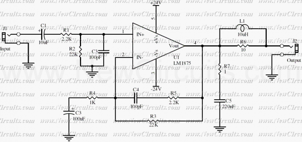
This simple 20 watts audio power amplifier is designed for home-brewed purpose. The L1 should be able to handle a current up to 4A to drive speaker in full load. The distortion is 0.015% @ 1KHz / 20W. This...
This monolithic IC, class-B audio amplifier circuit is a 6-W car radio amplifier for use with 4-ohm and 2-ohm load impedances. The monolithic integrated circuit (IC) described is designed to function as a Class-B audio amplifier, specifically tailored for...
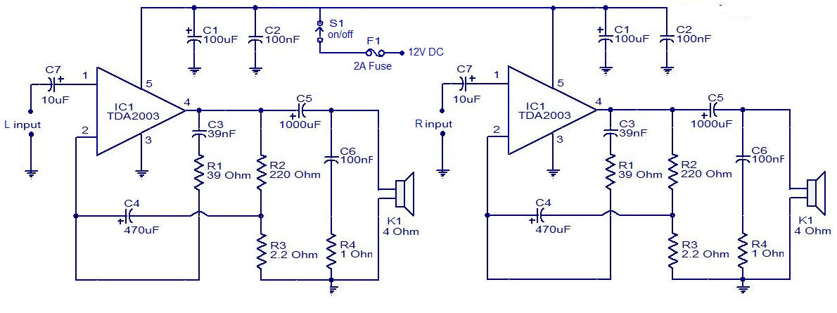
The circuit is easy to construct. The TDA2003 is an integrated radio amplifier from ST Microelectronics that features short circuit protection for all pins, thermal protection, low harmonic distortion, and low crossover distortion. In the circuit provided, the TDA2003...
The MP3 files (up to 65,536) are stored on a micro SD card. This embedded MP3 module is a universal and compact circuit (37 mm x 27 mm) designed for playing MP3 audio files. The MP3 module can be...
Warning: include(partials/cookie-banner.php): Failed to open stream: Permission denied in /var/www/html/nextgr/view-circuit.php on line 713
Warning: include(): Failed opening 'partials/cookie-banner.php' for inclusion (include_path='.:/usr/share/php') in /var/www/html/nextgr/view-circuit.php on line 713