
Hum Filter Remove AC Line Noise Pre Amp Circuit for Hi-Fi Amplifier Audio Systems
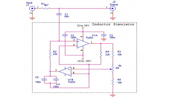
The circuit described serves as an effective solution for mitigating hum noise in audio systems, particularly in environments where interference from AC power lines is prevalent. The notch filter operates by selectively attenuating frequencies around the target frequency, which is essential for reducing unwanted noise without significantly affecting the overall audio quality. The use of operational amplifiers allows for a compact design while maintaining the necessary performance characteristics of the filter.
To implement this circuit, attention must be paid to the values of the resistors and capacitors used. The selection of R2, R4, C4, and C5 directly influences the performance of the filter. The calculated equivalent inductance, which is critical for determining the cutoff frequency, should be carefully designed to ensure it aligns with the target frequency of 50 Hz or 60 Hz, depending on the regional power line frequency.
The placement of C2 and C3 is vital for the stability of the op-amp. These capacitors should be positioned as close as possible to the power supply pins to reduce the impact of any voltage fluctuations or noise that may be introduced from the power supply. This practice helps to ensure that the op-amp operates within its optimal parameters, further enhancing the effectiveness of the notch filter.
Finally, the adjustment of the R6 potentiometer allows for fine-tuning of the filter's response, enabling the user to adapt the circuit to specific conditions or sources of hum noise. This flexibility is particularly useful in environments where the characteristics of the noise may vary, ensuring that the hum can be effectively managed. The schematic diagram accompanying this description visually represents the circuit layout and component connections, providing a clear guide for implementation.That hum noise is produced by electronic device with improper design, yes you`re right. And you might choose to solve the trouble maker, the source. You begin to check the grounding, the cabling, casing, and many more things you can do to eliminate the hum heard from your amplifier. You might put yourself into a trouble if the hum can`t be elimina ted and you don`t realize that the source is not come from your equipment that you have the access to fix it. For the source come from mp3 player powered by you AC to DC adapter, you might check for the ripple from your power adapter and fix it by adding a good regulator.
If you find that the source is coming from your television audio output or from your desktop PC sound card, and you don`t want to thinker them, then the circuit in this article would be very helpful. The circuit is a notch filter, a filter that remove a spot (or a very small) area in the frequency domain.
Ideally the notch filter remove only a single frequency, but practically it also attenuate other frequency around the spot. The circuit is based on inductor simulation using active component (op-amp). The equivalent inductor value simulated by this circuit is R2xR4x(C4+C5). You can replace the circuit in the dashed box by a single component: an inductor. Here you find that small component count in electronic circuit design is not always good, because you need an inductor with 150 Henry to replace the simulator circuit to notch out the 50 Hz signal, it`s hard to imagine how big its size and how expensive its price is.
Make sure that C2 and C3 are placed as close as possible to the op-amp power (Vcc and -Vcc) pins to stabilize the supply from glitch noise. You should adjust R6 potentiometer slowly to set the cut frequency at your power line frequency. The hum noise, in the most cases, is caused by AC power line noise, a static frequency around 50-60 Hz, depending on the system on your country.
The circuit schematic diagram is shown in the figure below. 🔗 External reference
Related Circuits
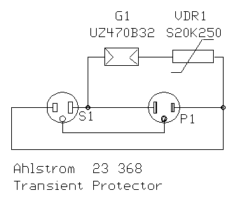
The following circuit is a schematic of a mains surge suppressor manufactured by Strömfors and sold under the model name "Ahstrom Transienttisuoja 23 386". It is designed to protect sensitive electronic devices against overvoltage transients in standard mains voltage...
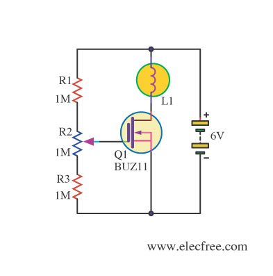
Changing the value of R2 alters the intensity of the lamp in this circuit, demonstrating the utility of a MOSFET as a variable resistor. An N-Channel Power MOSFET, designated as Q1, is utilized in the circuit. The specific part...
JFET iPod preamplifier, DIY Hi-Fi, schematic The JFET iPod preamplifier circuit is designed to amplify the audio signal from an iPod or similar portable audio device, enabling it to drive higher impedance loads such as amplifiers or speakers. This circuit...
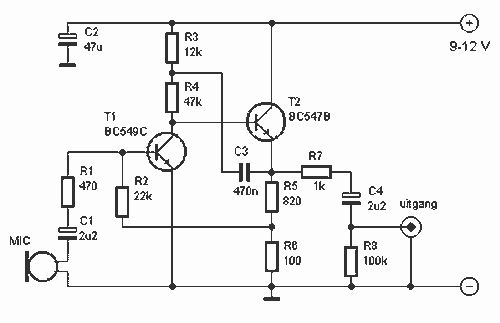
This preamplifier amplifies the signal from a microphone, an amplifier so that it can be further strengthened. The circuit supplies an output signal line. With two transistors, it is not difficult to build such a circuit. The amplifier produces...
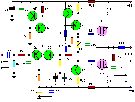
This is a 25-watt basic power amplifier designed for ease of construction at a reasonable cost. It outperforms the standard STK module amplifiers commonly found in mass-market stereo receivers today. The design was initiated to create a 25-watt amplifier...
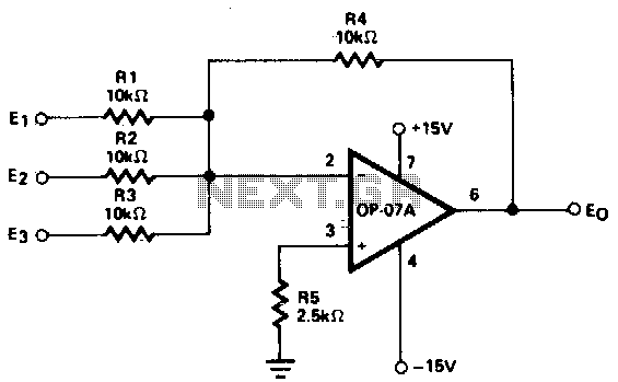
This circuit generates continuous outputs that depend on multiple input variables. The circuit in question typically employs a combination of operational amplifiers (op-amps), resistors, and potentiometers to achieve its functionality. The outputs can be tailored based on the variations...