
30mA LED Dimmer
The circuit design utilizes an LM358 operational amplifier to create a reliable current source for driving LEDs effectively. The first half of the LM358 serves to buffer the reference voltage generated by the low-current LED (D1), which stabilizes the voltage level for the current source. The second half of the LM358 is configured as a current source, allowing for precise control of the output current supplied to the LED.
The potentiometer is connected in such a way that it varies the voltage at the non-inverting input of the op-amp, thereby controlling the output current. The resistor R2 is strategically placed to sense the current flowing through the LED, ensuring that the current remains within the desired range. The relationship between the resistance of R2 and the current through the LED can be adjusted to accommodate various LED specifications, making this circuit versatile for different applications.
When multiple LEDs are connected in series, the voltage drop across each LED must be considered in conjunction with the total supply voltage. The calculated maximum number of LEDs that can be connected in series is contingent upon the available supply voltage and the voltage drop across the series resistor R1. Increasing the supply voltage to 30 V allows for a greater number of LEDs; however, care must be taken to ensure that R1 is adjusted accordingly to prevent excessive current from damaging the reference LED.
The thermal performance of the LM358 must also be monitored, especially when driving larger LED arrays. The maximum power dissipation of 830 mW for the DIP version indicates that the circuit must be designed to operate within safe limits to prevent overheating. Calculating the power consumption using the given formula ensures that the design remains efficient and reliable, facilitating safe operation across various configurations. This current source circuit is ideal for applications requiring dimmable LED lighting, providing smooth and linear brightness control.If you`ve ever tried dimming a LED with a simple potentiometer, you know that the approach does not work very well. Just as with ordinary diodes, the voltage-current characteristic of LEDs is far from linear. The result depending on the potentiometer setting the LED brightness will hardly change most of the time as the pot is turned and a sudden variation at the end.
The best method to tackle this problem is to power the LED from a current source with zero to 100% adjustment range. The circuit shown here is an example. A low-current LED (D1) is used to generate a reference voltage that`s first buffered by one half of an LM358.
The actual current source that powers the LED is built around the second opamp in the chip. The potentiometer allows the output current to be adjusted, with R2 acting as a current sense, the resistor dropping the same voltage as the one obtained from the pot. Using Ohm`s law we find that the maximum current through R2 amounts to about 29 mA (I LED = 1. 6 V / 56 ©). If necessary, the current may be adapted to suit other LED types, for example, 20 mA is obtained with R2 = 82 © and 10 mA at R2 = 150 ©.
It is also possible to connect several LEDs in series. The total voltage available for the LEDs is determined by the voltage drop across series resistor and the opamp, and, of course, the supply voltage. In this way, the highest number of LEDs may be found from ULED, total = Ubatt 5. 1 V. In principle, it is possible to increase the supply voltage to 30 V in order to connect even more LEDs in series.
This does, however, call for the value of series resistor R1 to be increased to prevent overloading the low-current LED used in the voltage reference. If you intend to experiment with larger numbers of LEDs (say, in arrays) then the maximum loading of the opamps becomes an issue.
The DIP version of the LM358 may dissipate up to 830 mW. The power, P, is calculated from P = Ubatt 1. 6 ULED, total G— I LED, max. 🔗 External reference
Related Circuits
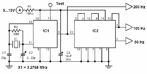
This circuit generates a 50 Hz timebase signal that is independent of the power line frequency. It is designed to provide the 50 Hz signal for electronic circuits that operate specifically with this clock frequency, primarily for circuits and...
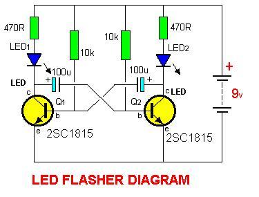
2SC1815 Flip Flop LED Flasher is a very simple and easy-to-understand circuit. The 2SC1815 Flip Flop LED Flasher circuit utilizes a 2SC1815 transistor, which is a general-purpose NPN transistor, to create a basic LED flasher. This circuit operates on the...
The optically-controlled circuit plays a crucial role in urban street lighting and corridor illumination. By utilizing this circuit, lighting lamps can be automatically turned on and off based on ambient light levels, thereby reducing the need for manual control,...
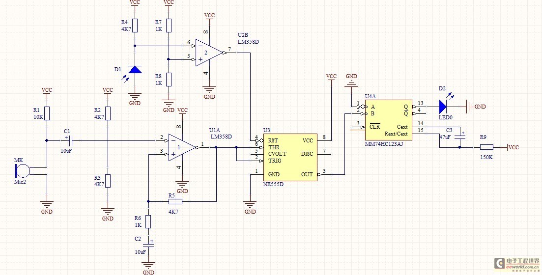
This circuit is constructed around a 555 timer and utilizes very few components. Due to its simplicity, even beginners can easily assemble and use it as a control device. A readily available laser pointer can be employed to operate...
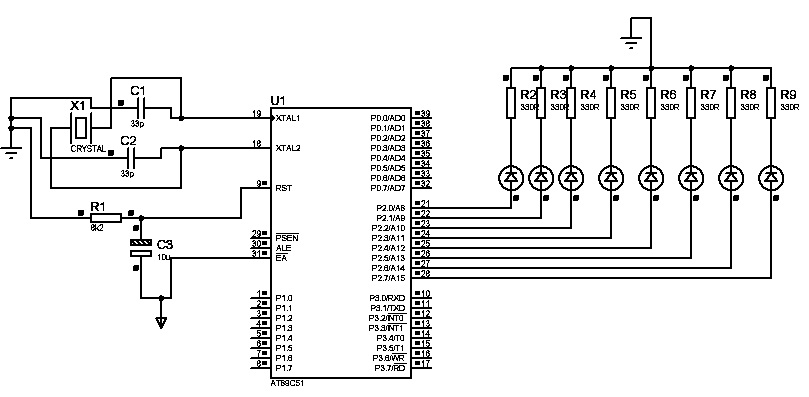
The first "Hello World!" project preferred for microcontrollers is LED blinking. An ATMEL 89C51 (40-pins DIP) microcontroller, based on the 8051 architecture, is used, which is ideal for first-time learning of MCU chips. The program is very simple and...
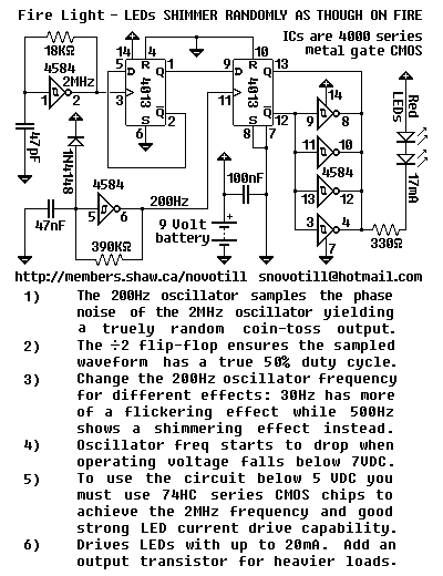
This may well be the world's only discreet logic circuit to generate truly random output. It makes an excellent candle flicker light for your Halloween pumpkin and looks much more authentic than a shimmer light wherever a good simulated...
Warning: include(partials/cookie-banner.php): Failed to open stream: Permission denied in /var/www/html/nextgr/view-circuit.php on line 713
Warning: include(): Failed opening 'partials/cookie-banner.php' for inclusion (include_path='.:/usr/share/php') in /var/www/html/nextgr/view-circuit.php on line 713