
crystal controlled timebase
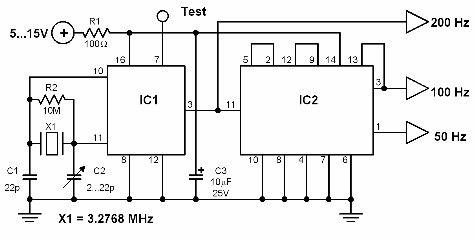
The circuit operates by utilizing a crystal oscillator to produce a stable frequency, which is then divided down to the desired 50 Hz output. The crystal oscillator, represented by IC1, generates a high-frequency signal that is determined by the characteristics of the crystal used. This high frequency is essential for maintaining accuracy and stability in the timing applications. IC2, serving as a frequency divider, takes the output from IC1 and reduces it to the required 50 Hz frequency by dividing the input frequency by a specific factor.
The trimmer capacitor C2 plays a critical role in fine-tuning the circuit. It allows for minor adjustments to the oscillator frequency, ensuring that the output remains precise. The calibration process is straightforward, enabling users to achieve the desired frequency with minimal effort. By employing a digital frequency counter, the user can accurately monitor the output frequency and make the necessary adjustments to C2.
This circuit finds applications in various electronic devices that require precise timing signals, such as clocks, timers, and other timing-critical systems. Its independence from the power line frequency makes it particularly useful in regions where the power line frequency may vary or in applications where a stable timing reference is essential. Overall, this circuit design provides a reliable solution for generating a 50 Hz timebase signal, ensuring compatibility with European electronic standards and enhancing the performance of timing applications.This circuit provides a 50 Hz timebase signal that is independent from the power line frequency. It is designed to provide the 50 Hz signal for electronic circuits which function only with this clock frequency (mostly circuits and electronic devices with european standards). It is popularly used for clock and timing applications. By carefully anal ysing the circuit diagram, you can see that IC1 works as crystal controlled oscillator while IC2 functions as a 214 divider. The crystal frequency can be finely adjusted within 20 Hz range through the trimmer capacitor C2. Calibration is simple and can be done in two different ways. First method: if you have a digital frequency counter, connect it to pin 7 of IC1 (TEST output on the printed circuit board) and adjust trimmer cap C2 until the frequency being displayed is 204.
800 Hz. 🔗 External reference
Related Circuits
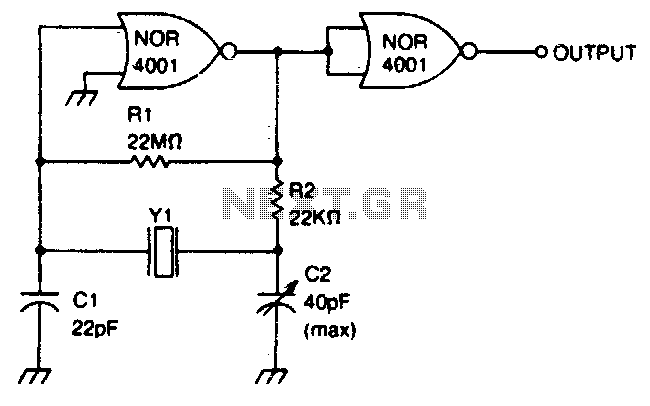
This circuit operates within a frequency range of 0 MHz to 2 MHz. The frequency can be finely adjusted to a specific value using the trimmer capacitor C2. Additionally, the second NOR gate functions as an output buffer. The circuit...
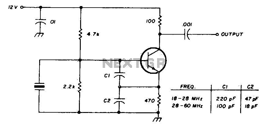
International Crystal OF-1 HI oscillator circuit for third-overtone crystals. The circuit does not require inductors. The International Crystal OF-1 HI oscillator circuit is specifically designed to operate with third-overtone crystals, which are capable of generating higher frequency oscillations compared to...
The transformer is a 220V to 12V, 50Hz, and 3.6VA PCB type transformer. The model depicted is HRDiemen E3814056. Being encapsulated, it is isolated from external influences. A 250V 400mA glass fuse protects the circuit from damage caused by...
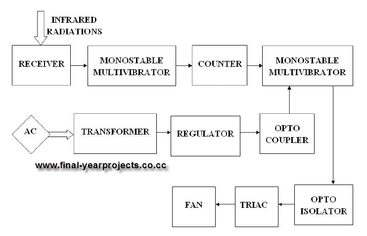
This report presents a comprehensive overview of a mini project titled "Remote Controlled Fan Regulator," developed in accordance with the curriculum requirements for the sixth semester of the Bachelor of Technology degree in Electrical and Electronics Engineering. The report...
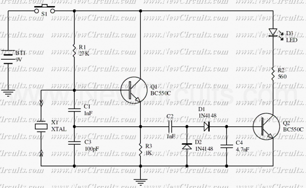
This is a simple XTal tester circuit. T1 and XTal have formed an oscillator. C1 and C2 are voltage divider for oscillator. if the XTal is safe, the oscillator will work well and its output voltage will be rectified...
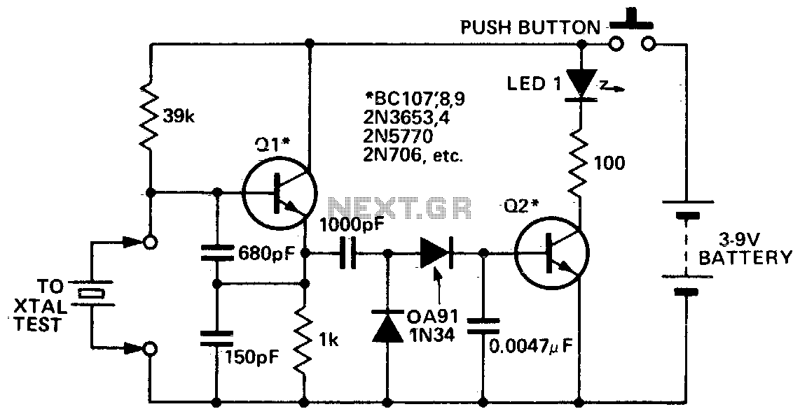
This circuit is designed to check fundamental oscillations. When Q2 conducts, the LED lights up. It operates with A3 HF crystals on a "Go-No-Go" basis. An untuned or 6V, 40mA bulb can be used in place of the Colpitts...