
333 joule moc capacitor bank
The capacitor bank described is a high-voltage energy storage system designed for experimentation with short circuits. It utilizes microwave oven capacitors, which are not typically intended for such applications but can be repurposed for short-duration high-voltage discharges. The bank is constructed with careful attention to safety and performance, employing heavy gauge wiring and a robust connection strategy to handle the expected high currents. The design incorporates a mechanism for rapid discharge, which is critical to prevent potential hazards associated with stored energy in the capacitors. The use of a spring-loaded trigger for short-circuiting the capacitors into a coil adds an innovative approach to controlling the discharge process, allowing for a more manageable and safer execution of high-energy experiments. Overall, this capacitor bank represents a complex and potentially dangerous system that requires thorough understanding and caution in operation.The idea behind a capacitor bank is to charge up as much energy as possible to short circuit that energy through small coils, aluminium paper, steel wool, wire and a lot of other things that can conduct a electric current. The short circuit current is enormous for a very short time and that big amount of energy can turn the conducting paths material into vapour.
Microwave oven capacitors capacity is relatively low for their voltage rating, but they are designed to be applied around 300% of their rated DC voltage for 60 seconds. Most are rated 2100VAC at about 0, 8 to 1 uF capacity. Microwave oven capacitors got a built in bleeder resistor which discharges the capacitor fast, which is why its important to discharge the bank as fast as possible when the wanted voltage is stored over the bank.
On the other hand its a good safety feature that the bank will discharge itself within 30 seconds and that might save your life. The amount of microwave ovens needed to build this bank is over the edge, but as they can be obtained for free from containers its still worth the time for the sake of the experiments.
Microwave oven capacitors are not build to sustain these hard short circuits, so they will take damage for each short circuit in the form of lowered capacity as the dielectric material in the capacitor is damaged, this might end fatal with a shorted capacitor that in the worst case will happen with a violent explosion. Take care to shield off the capacitors as they are housed in a metal can, fragments from these is not something you want flying around you if there is a failing capacitor.
With the knowledge of the capacitors being designed to work with voltages 300% higher than their ratings for shorter periods of time, I have chosen to charge them to 6000 VDC as its convenient to build a charger for this voltage. This voltage can be achieved with a microwave transformer with a full-wave voltage doubler on the secondary side.
The transformer delivers 2300VAC RMS. The bleeder resistors in the capacitors loads the transformers and brings the voltage down to 6000VDC when its charging on the 21 capacitors my bank consists of. The 21 capacitors are not the same make or capacity, but varies from 0, 85 to 1 uF. I have measured the the capacity of the bank to be 18, 5 uF with a LCR meter, the stored energy in the bank is then.
The capacitors are split into 3 strings with 7 capacitors in each. I soldered 4mm ² copper wire between the terminals of the 7 capacitors and the 3 strings are connected with 6mm ² wire bringing all 21 capacitors into a parallel coupling. Heavy gauge wire is used to ensure that it can withstand the huge current doing the short circuit and it gradually gets heavier the further into the connection towards the short circuit point we get.
All connections are intended to be as round as possible to avoid corona losses when working with voltage into the kV range. As mentioned the capacitors got a built in bleed resistor which makes it crucial that the discharges happens very fast after charging is over.
A solution could be to keep charging while discharging, but this poses new problems where we have to protect the charger circuit against the ringing current when the capacitors are short circuited. I chose to make a spring loaded trigger that is pulled to the charger and when I let it go it springs to a brass plate where it short circuits the capacitors into the coil, look at the picture underneath and the schematics to get a better understanding.
Now that everything is put together and calculations have been done to some extend, its time to harvest the sweet fruits in the shape of wonderful bangs, sparks and explosions. To get fully rewarded it is necessary to have 🔗 External reference
Related Circuits
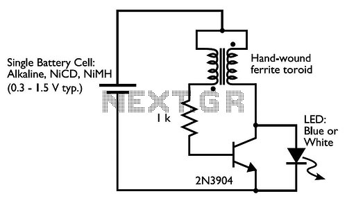
Drive a blue or white LED from a low voltage. Typically, lighting a blue or white LED requires a voltage of 3 to 3.5 V, which can be supplied by a 3 V lithium coin cell. However, a 1.5...
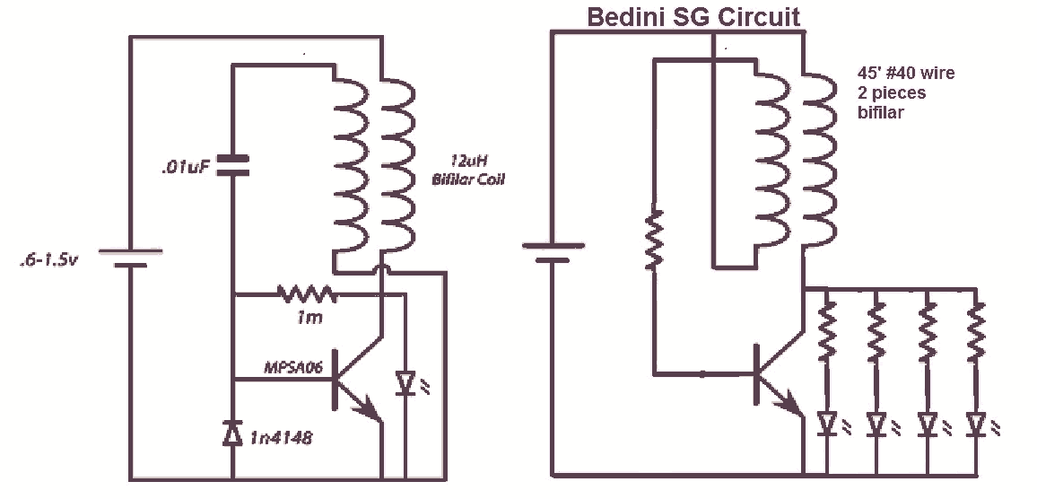
It would be beneficial to obtain schematics of the Joule Thief and Bedini oscillator circuit connections. This is an area that has not been previously explored. The schematic on the left was sourced from the Energetic Forum, while the...
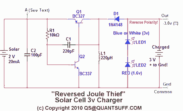
This design presents an innovative approach to the Joule Thief (JT) circuit typically utilized in garden lights. Instead of directly charging a 1.2V battery from the solar cell and converting the power to operate a 3-volt LED, this circuit...
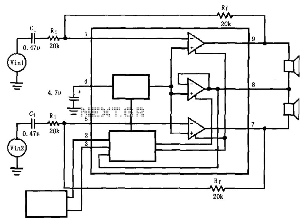
The LM4911 is presented in a configuration that does not utilize an output capacitor (OCL) for its power circuit. This design eliminates the need for squelch control (Mute), as the shutdown control (SD) responds more rapidly than the squelch...
High voltage electrolytic capacitors in valve equipment can deteriorate if the equipment is unused for an extended period. This deterioration manifests as reduced capacitance and significantly increased leakage current. In some instances, the capacitor may become nearly short-circuited. Using...
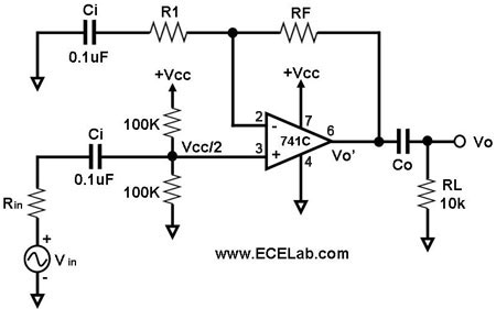
All the capacitors are present to block DC signals; however, the values of capacitance are crucial, and it is necessary to determine the value of Co. Rin denotes the source resistance, which is not an integral part of the...