
4 20ma current loop tester
The circuit design incorporates a microcontroller, specifically a PICAXE, which is central to managing the operation of the 4-20mA signal injector. The microcontroller is programmed to handle the PWM signal generation, which is crucial for controlling the current through the transistor Q1. The low-pass filter, comprised of a 1kΩ resistor and a 4.7μF capacitor, smooths the PWM signal into a stable analog voltage. This analog voltage directly influences the current flowing through the load, allowing precise control over the output current levels.
The feedback mechanism is essential for maintaining accuracy in the output current. The 100Ω resistor, placed in series with the emitter of Q1, converts the output current into a measurable voltage signal that the microcontroller can read. This voltage is then processed by the microcontroller's analog-to-digital converter, enabling the system to dynamically adjust the PWM duty cycle based on real-time feedback.
The inclusion of an alarm state when an open circuit is detected enhances the safety and reliability of the device. This feature prevents potential damage to the circuit under test and alerts the operator to rectify the issue. The LED indicators provide essential operational feedback, allowing technicians to monitor the device's status visually.
Powering options for the circuit are versatile, accommodating both portable and stationary applications. The use of two 9V batteries makes it suitable for fieldwork, while a 12V DC plug pack can be utilized for laboratory testing, ensuring flexibility in various operational environments. Overall, this design presents a practical solution for technicians requiring a reliable and cost-effective method for simulating 4-20mA signals in their work with pneumatic valves and similar devices.This design will interest technicians who work on pneumatically operated valves and other 4-20mA current loop controlled devices. Although 4-20mA signal injector/calibrators are available, this one is both cheap to build and easy to operate.
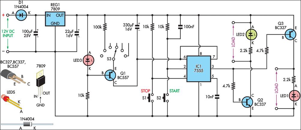
When first powered up, the circuit sinks 4mA of current. If switch S1 is pressed, the current level slowly ramps up to 20mA, pauses and then ramps back to 4mA. This cycle will continue unless the switch is pressed again, whereby the output will lock to its current level. A further push of the switch resumes the prior cyclic operation. Output2 from the micro (IC1) is programmed to generate a pulse-width modulated (PWM) signal to drive the current sink transistor (Q1).
The digital PWM signal is converted to an analog voltage using a low-pass filter formed by the 1k ‰ series resistor and a 4. 7 F tantalum capacitor. By varying the PWM duty cycle and therefore the DC signal level out of the filter, the program can indirectly vary the current flow through the transistor.
A 100 resistor in series with the emitter of Q1 converts the loop current to a small voltage, which is fed into the micro on input1. The program uses this feedback signal to zero in on the desired current level with the aid of the micro`s analog-to-digital converter.
Details of this can be seen in the accompanying program listing. If the PICAXE senses an open circuit, it shuts down the output and goes into an alarm state, to alert the operator and protect the circuit under test. The switch can be pressed to reset operations to the start once the open circuit has been rectified. The LED flashes a code for various milestones, as follows: one flash at 4m and one flash to confirm a switch press two flashes at 12m when ramping up (for the first 5 cycles); three flashes at 20m and continued fast flash sequence for open-circuit alarm.
For portable use, the circuit can be powered from two 9V batteries, whereas for bench testing, a 12V DC plugpack will suffice. 🔗 External reference
Related Circuits

All ATL-3 loop windings are center-tapped and balanced with respect to their amplifier/receiver chassis ground, which leads to self-cancellation of electric field interference. Magnetic noise fields, such as those from televisions and electric meter boxes, or electromagnetically radiated interferences,...
A loop antenna is a radio antenna made up of a loop (or loops) of wire, tubing, or other electrical conductor with its ends connected to a balanced transmission line. This design includes two distinct types of antennas: the...
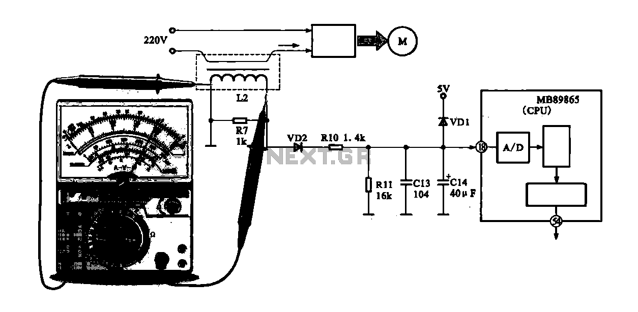
A current-voltage conversion circuit is commonly utilized in current detection applications. An example is the current detection circuit for a ring inverter air conditioner, which primarily serves to monitor the supply current of the compressor motor. Excessive current can...
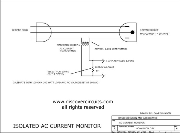
This circuit utilizes a small AC current transformer from Magnetek to generate an isolated voltage that is proportional to the AC current flowing through the primary winding. The AC current transformer operates on the principle of electromagnetic induction, where the...
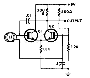
L1 is a loop consisting of 10 to 20 turns of insulated wire with a diameter ranging from 4 inches to 4 feet. The oscillator frequency, which operates between 7 to 30 MHz, varies significantly when an individual approaches...
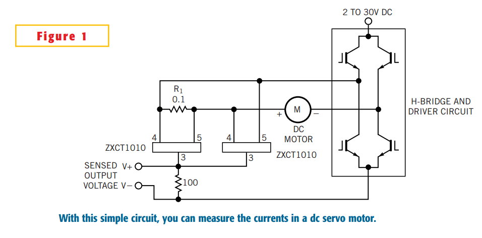
The simple circuit design in Figure 1 lets you measure all components of a current flowing in a dc servo motor. The rectified output of the circuit uses ground as a reference, so you can measure the output by...