
Circuit measures currents in dc servo motor
The described circuit is designed for precise current measurement in a DC servo motor application. The use of a current-sense resistor, R1, valued at 0.1 ohms, is critical for developing a voltage drop proportional to the current flowing through the motor. This voltage drop is then processed by the Zetex ZXCT1010 integrated circuit, which is specifically designed for current sensing applications.
The ZXCT1010 operates by taking the differential voltage across the current-sense resistor and converting it into a single-ended output. This functionality is essential because it simplifies the interfacing of the circuit with a single-ended Analog-to-Digital (A/D) converter, allowing for easier integration into microcontroller systems or digital signal processors. The dual configuration of the ZXCT1010 ICs serves as a signal rectifier, ensuring that the output signal is suitable for accurate measurement.
The design leverages the ground as a reference point, which is a common practice in electronic measurement systems. This approach minimizes the complexity of the circuit and reduces the number of required components. The overall design is optimized for cost, size, and power efficiency, making it ideal for applications where space and energy resources are limited.
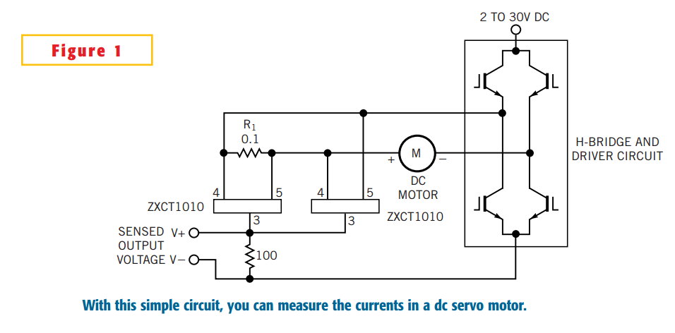
In summary, this circuit design provides a robust solution for measuring current in DC servo motors, utilizing the ZXCT1010 IC for effective signal conversion and ensuring compatibility with single-ended A/D converters. The choice of a low-value current-sense resistor enhances the circuit's sensitivity while maintaining a compact footprint, suitable for various electronic applications.The simple circuit design in Figure 1 lets you measure all components of a current flowing in a dc servo motor. The rectified output of the circuit uses ground as a reference, so you can measure the output by using a single-ended A/D converter.
The current-sense resistor, R1, has a value of 0.1. The Zetex (www.zetex.com) ZXCT1010 IC converts the differential signal across R1 to a single-ended signal. Two of these ICs form a signal rectifier. The single-ended signal makes measurement by an A/D converter cost-effective, small, and frugal in power consumption.
🔗 External reference
Related Circuits
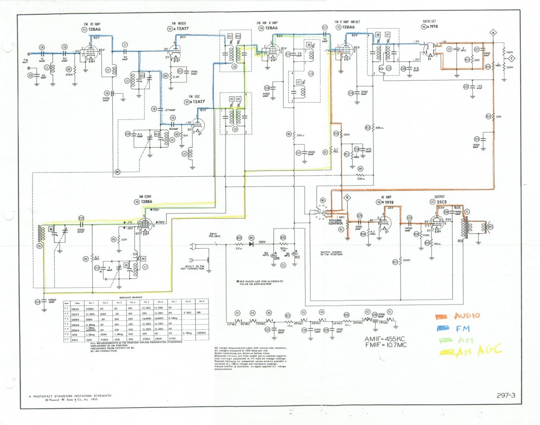
This document outlines the restoration of an antique AM/FM Granco 720 radio. It explores the design of the AM and FM receivers, detailing the alignment of these receivers, discussing repairs, and evaluating the radio's performance. The restoration of antique...

This circuit is designed as a countdown timer utilizing a countdown calculation. It employs the 555 integrated circuit (IC) as the primary control element. The 555 IC functions as a counter and a transistor switch to activate a relay...
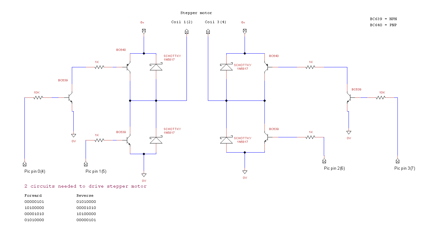
miRover. This page details how to use a PIC microcontroller and an H-bridge or an L298 to drive a bipolar stepper motor. The project involves utilizing a PIC microcontroller to control a bipolar stepper motor, which is commonly used in...
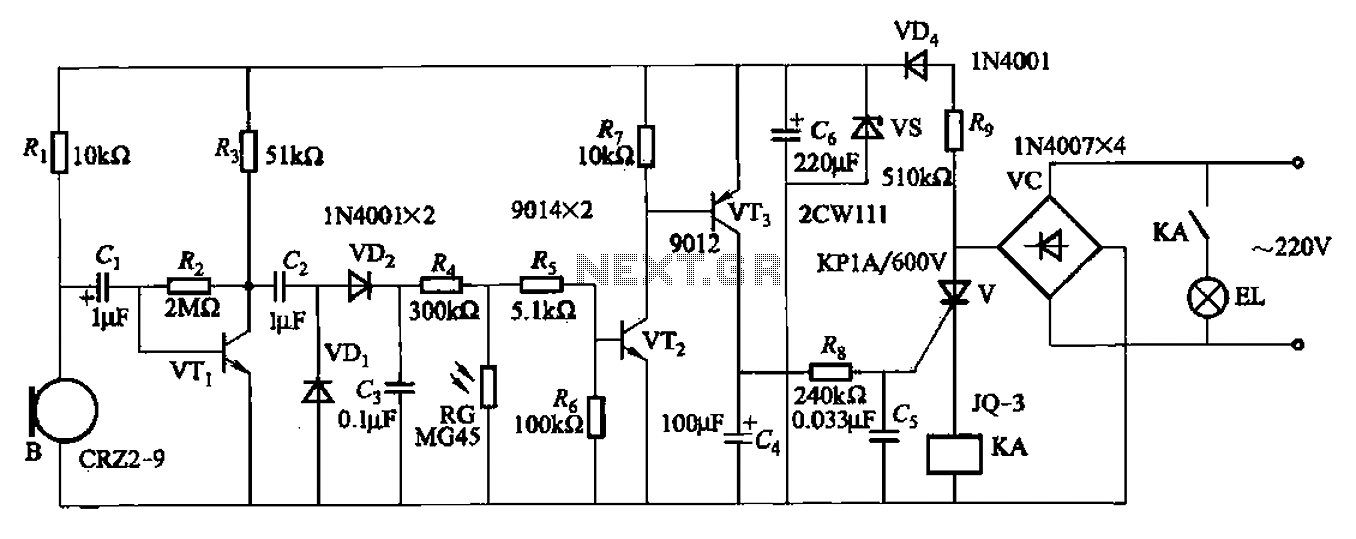
A resistor R8, capacitors Cd, and a thyristor V AC switch form a delay circuit. The lamp's lighting delay time is determined by the resistor Rs and capacitor C4, with a delay of approximately 40 seconds as indicated in...
A simple whole house FM transmitter circuit diagram and description. Operating power is a 1.5V battery of any type. This circuit is able to transmit at a distance of 30 meters. The whole house FM transmitter circuit operates on a...
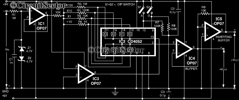
This circuit is a precision amplifier with digital control, designed for signal conditioning of low-output transducers operating in the millivolt range. The resistors R3 to R6 can be user-selected, with values ranging from 1 kilo-ohm to 1 mega-ohm, allowing...