
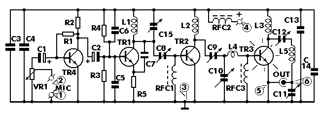
4 Watt FM Transmitter
The construction of electronic circuits on a printed circuit board (PCB) involves a thin insulating material coated with a layer of conductive copper, configured to form the necessary connections between components. Utilizing a well-designed PCB significantly accelerates the construction process and minimizes the likelihood of errors. Smart Kit boards are pre-drilled, with component outlines and identifications printed on the component side to facilitate assembly. To prevent oxidation during storage and ensure the board arrives in optimal condition, the copper is tinned during manufacturing and coated with a special varnish that protects against oxidation and simplifies soldering. Soldering components to the board is essential for circuit assembly, and success largely depends on the technique employed. A lightweight soldering iron with a maximum power of 25 Watts should be used, featuring a fine tip that must be kept clean. Specially designed wet sponges are effective for cleaning the hot tip, allowing for the removal of accumulated residues. It is advised not to file or sandpaper a dirty or worn-out tip; if cleaning is unsuccessful, replacement is necessary.This is a small but quite powerful FM transmitter having three RF stages incorporating an audio preamplifier for better modulation. t has an output power of 4 Watts and works off 12-18 VDC which makes it easily portable. It is the ideal project for the beginner who wishes to get started in the fascinating world of FM broadcasting and wants a good
basic circuit to experiment with. As it has already been mentioned the transmitted signal is Frequency Modulated (FM) which means that the carrier`s amplitude stays constant and its frequency varies according to the amplitude variations of the audio signal. When the input signal`s amplitude increases (i. e. during the positive half cycles) the frequency of the carrier increases too, on the other hand when the input signal decreases in amplitude (negative half-cycle or no signal) the carrier frequency decreases accordingly.
In figure 1 you can see a graphic representation of Frequency Modulation as it would appear on an oscilloscope screen, together with the modulating AF signal. The output frequency the transmitter is adjustable from 88 to 108 MHz which is the FM band that is used for radio broadcasting.
The circuit as we have already mentioned consists of four stages. Three RF stages and one audio preamplifier for the modulation. The first RF stage is an oscillator and is built around TR1. The frequency of the oscillator is controlled by the LC network L1-C15. C7 is there to ensure that the circuit continues oscillating and C8 adjusts the coupling between the oscillator and the next RF stage which is an amplifier. This is built around TR2 which operates in class C and is tuned by means of L2 and C9. The last RF stage is also an amplifier built around TR3 which operates in class C the input of which is tuned by means of C10 and L4.
From the output of this last stage which is tuned by means of L3-C12 is taken the output signal which through the tuned circuit L5-C11 goes to the aerial. The circuit of the preamplifier is very simple and is built around TR4. The input sensitivity of the stage is adjustable in order to make it possible to use the transmitter with different input signals and depends upon the setting of VR1.
As it is the transmitter can be modulated directly with a piezoelectric microphone, a small cassette recorder etc. It is of course possible to use an audio mixer in the input for more professional results. First of all let us consider a few basics in building electronic circuits on a printed circuit board.
The board is made of a thin insulating material clad with a thin layer of conductive copper that is shaped in such a way as to form the necessary conductors between the various components of the circuit. The use of a properly designed printed circuit board is very desirable as it speeds construction up considerably and reduces the possibility of making errors.
Smart Kit boards also come pre-drilled and with the outline of the components and their identification printed on the component side to make construction easier. To protect the board during storage from oxidation and assure it gets to you in perfect condition the copper is tinned during manufacturing and covered with a special varnish that protects it from getting oxidised and also makes soldering easier.
Soldering the components to the board is the only way to build your circuit and from the way you do it depends greatly your success or failure. This work is not very difficult and if you stick to a few rules you should have no problems. The soldering iron that you use must be light and its power should not exceed the 25 Watts. The tip should be fine and must be kept clean at all times. For this purpose come very handy specially made sponges that are kept wet and from time to time you can wipe the hot tip on them to remove all the residues that tend to accumulate on it.
DO NOT file or sandpaper a dirty or worn out tip. If the tip cannot be cleaned, r 🔗 External reference
Related Circuits
Here is the schematic for an 8 watt audio amp. This amp can be used as a simple booster, the heart of a more complicated amplifier or used as a guitar amp. The circuit can be built on a...

A high-quality stereo FM transmitter circuit is presented here. The circuit utilizes the IC BA1404 from ROHM Semiconductors. The BA1404 is a monolithic FM stereo modulator that incorporates a built-in stereo modulator, FM modulator, and RF amplifier circuitry. The...
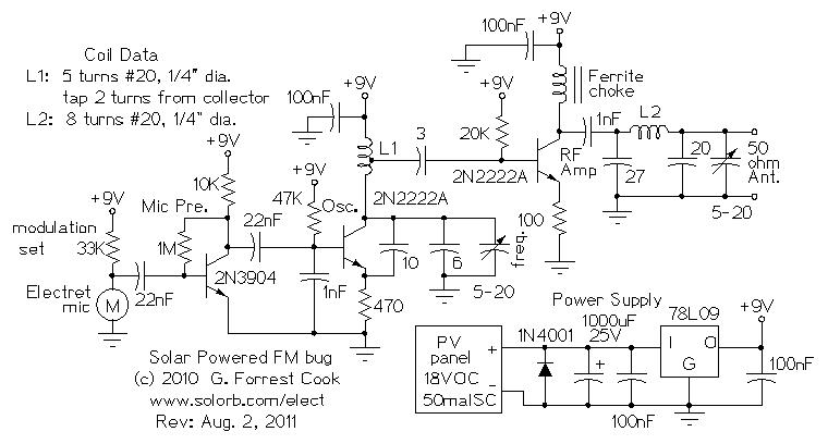
Numerous miniature FM transmitter bug circuits are available online; however, this particular design is distinctive as it operates entirely on solar power, eliminating the need for a battery. The transmitter will function as long as sunlight is incident on...
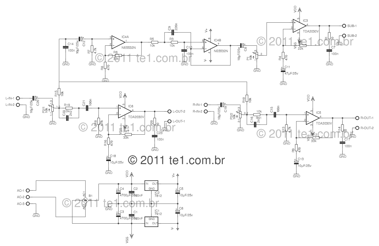
This circuit is a complete application for a 2.1 amplifier system, consisting of two satellite speakers powered by a TDA2030 and one subwoofer. This 2.1 system is commonly utilized in commercial applications as an amplifier for computers, enhancing audio...
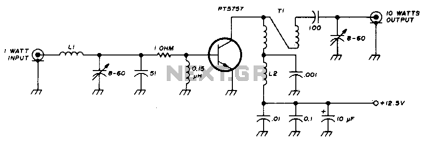
This 10-watt, 144-MHz power amplifier utilizes a TRW PT5757 transistor. The inductor LI consists of 4 turns of no. 20 enameled wire with a 3/32" inner diameter, while inductor L2 comprises 10 turns of no. 20 enameled wire with...
This is a handy, easy to build general purpose 50 watt amp. The amp has an input for a radio, TV, stereo or other line level device. It also has a phono input for a record player, guitar, microphone...