
Circuit Power audio Amplifier with TDA2030 2.1 Chanell 3 x 18 Watts Subwoofer Complete With PCB suggestion and power supply
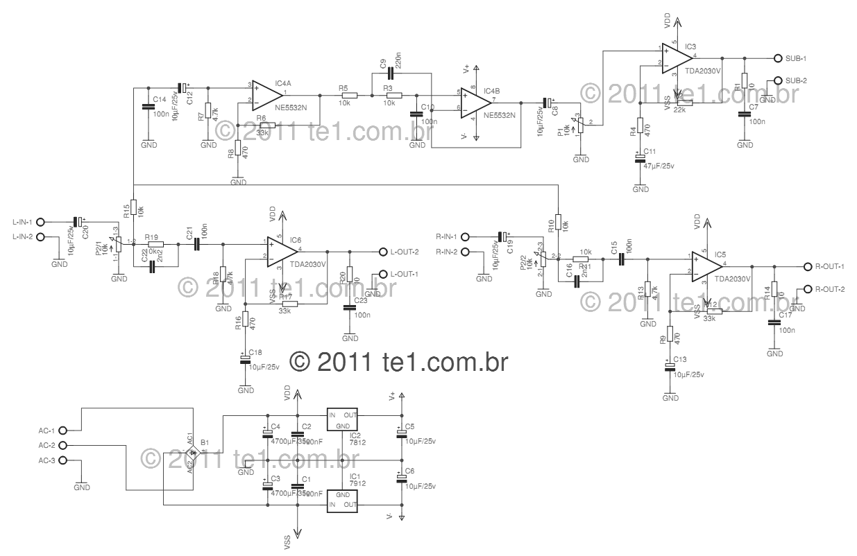
This 2.1 amplifier circuit is designed to provide a balanced audio experience, effectively separating low and high frequencies for optimal sound reproduction. The use of the TDA2030 integrated circuit for satellite speakers ensures efficient amplification with low distortion, making it suitable for various applications including home audio systems and computer setups. The power supply design, featuring a dual secondary transformer and robust filtering capacitors, ensures stable operation and minimizes noise, enhancing overall audio quality. The inclusion of feedback and compensation networks allows for fine-tuning of the amplifier's performance, accommodating different speaker configurations and user preferences. The NE5532 operational amplifier, known for its low noise and high gain characteristics, further improves the audio signal, ensuring that both satellite and subwoofer outputs are clear and powerful. This circuit exemplifies a well-rounded approach to audio amplification, combining reliability, efficiency, and high fidelity.This circuit is a complete application is 2. 1 amp, two satellite speakers for TDA and one for the subwoofer, making the 2. 1 system, widely used in commercial applications as an amplifier for computers, which may give an increased in its audio system with a stereo amplifier + bass amplifier (subwoofer). The power supply is of symmetric type, using a transformer, 110 or 220 with dual secondary 12 volts and 3A current. I recommend using a fuse and a switch before the transformer. B1 is a bridge rectifier least 100 volts / 4 A, an example that can be used is GBU606, the filtering circuit is formed of the capacitors C1, C2, C3 and C4, the electrolytes can have values from 4700 F. The power supply for the op amp Highpass filter, is used three terminal integrated circuits 7812 and 7912.
The left and right channels give exactly the same, let`s see how the left channel: LIN is the audio input jack, which is coupled by C20 to the pot volume adjustment, it is a double pot, and set the two channels simultaneously. R19/C22, helps to improve the signal of the treble. The capacitor C21 couples the signal to CI6 TDA2030, after amplified audio output is pin 4 of integrated.
The resistor R7 and R9 are responsible for feedback, so by changing the value of R7 can increase or decrease the gain of the amplifier. R20 and C23 form the compensation network for the speakers. The signal comes from the subwoofer to the left and right channels by resistors R15 and R10 being decoupled by capacitor C12, is applied in the operational amplifier 1 IC4A NE5532, which forms a pre-amplifier to boost the signal by 6 times.
Determined by R6/R8 resistor. The components C9, C10 and R10 form a low pass filter in this case is calculated to 200Hz. After leaving IC4B the low frequency audio through the potentiometer P1 that makes the volume level, then forwarded to IC3 is what makes the subwoofer amplifier, the operating principle is the same as satellite amplifiers. 🔗 External reference
Related Circuits
A servo is an error-sensing feedback control mechanism used to correct the performance of a system. A servo motor is a DC motor equipped with a servo mechanism. A servo motor is an electromechanical device that utilizes a closed-loop control...
This is a simple automatic light switch circuit designed for bedrooms. After construction, the input terminals of this circuit should be connected in parallel to the intended lighting fixture. The automatic light switch circuit utilizes a light-dependent resistor (LDR) as...
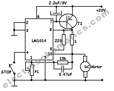
This motor speed controller utilizes a single IC, the LM1014, to regulate the speed of a DC motor. It detects the increase in motor current as the rotation of the motor increases. The motor speed controller is designed around the...
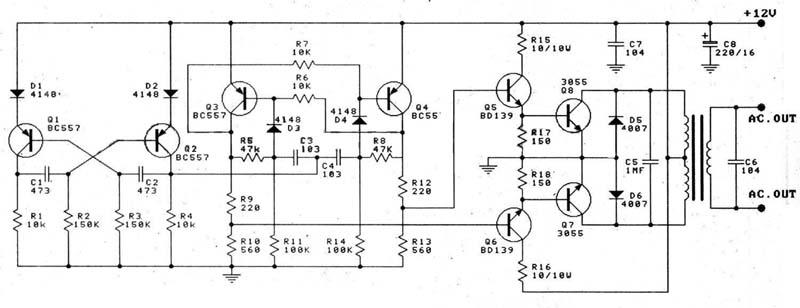
This circuit is a 100W DC inverter based on a transistored multivibrator and serves as a transistor signal amplifier. The inverter converts a 12V DC input voltage to approximately 220V AC. It is recommended to use a 12V car...
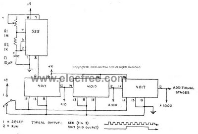
This circuit is designed to provide long time delays using the integrated circuit Timer 555. It utilizes the NE555 to generate pulse frequencies, which are then divided by a 4017 decade counter to achieve the desired delay. The component...
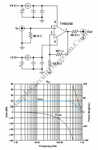
This circuit consists of wideband RF amplifiers that utilize current-feedback components such as the THS3202. The THS3202 was selected for its fast slew rate and wide bandwidth. The amplifier voltage gain of this circuit is 20, while the stage...