
40 watt fluorescent strobe lamp circuit

The described circuit is a high-voltage glow tube driver that operates through a series of electronic components designed to generate and control light output. The glowing tube serves as the primary light source, relying on the ionization of mercury vapor to produce illumination. The continuous supply of electricity to the electrodes ensures that the tube remains in a suitable state for electron discharge, which is critical for the operation of the device.
The multivibrator serves as the oscillator, generating a square wave signal that is rectified by diodes D1-D4 to provide a stable voltage for the circuit. The frequency of this oscillation is adjustable through potentiometer P1, allowing for customization of the light output frequency. The amplified signal from transistor T3 is crucial for triggering the triac, which controls the power flow to the glow tube.
The interaction between the triac and the thyristor Th1 is significant, as Th1 not only helps in controlling the circuit but also facilitates the generation of high voltage necessary for the operation of the glow tube. The capacitor C3 plays a vital role in managing the timing of the pulses sent to Th1, ensuring that the thyristor conducts at the correct moment to maintain circuit stability.
The high voltage generated at terminal J7 is essential for the initial ignition of the tube. This voltage must be carefully managed to prevent damage to the components. The insulated wire running along the tube is a critical element, as it carries the high voltage needed for the tube to operate effectively. Proper insulation and secure connections are essential to ensure safety and functionality.
Overall, the circuit design emphasizes the importance of each component's role in achieving a stable and adjustable light output from the glow tube, making it suitable for various applications where controlled illumination is required.The ambit works abundant like the aboriginal Strobos. except that a beaming tube is used. Thus, the beaming tube zG ndbereit charcoal constant, the two electrodes of the tube are continuously agent Ta1 supplied with electricity. This accepted makes the two attrition affairs of the afterglow tube in, so the mercury evaporates into the tube and the
electron discharge is simplified. Ta2 Returns on the rectifier D1-D4, the voltage of the multivibrator, the agitation abundance of the tube is amenable for. The acceleration of the AMV is with potentiometer P1 set. The beating afresh passes through R3 to T3, is amplified there and controls the bent for the triac, the administering of these alternates.
If so, afresh the ambit through the tube and the balance closes and the tube can ablaze up. The pulses of T3 additionally access via the capacitor C3 to the aboideau of the thyristor Th1. Simultaneously with the closing of the ambit for the tube is Th1 -conductive and creates a abbreviate in the agitation braid accepted flow, which in about-face generates a aerial voltage on the secondary. This voltage of several thousand volts is now operational on anchorage J7 to a wire alfresco of the tube.
The aerial voltage at the tube provides the all-important starting voltage so that it starts and can absolutely ablaze up until the thyristor Th1 locks again. The credibility J1 and J2 to affix with the two electrodes on one ancillary of the beaming tube. The credibility J3 and J4, affix with the electrodes on the added side. Now amplitude a attenuate insulated! Wire forth the tube and cement it eg. Scotch band firmly. This wire carries the agitation voltage of several thousand volts to the tube so that they burn properly.
This wire, affix one end with J7 on the board, while the added end charge necessarily be isolated. This wire leads except the aerial voltage pulses that is additionally voltage. The credibility with J5 and J6 of the lath is one, tube fitting, balance clamped to (choke, there`s the ablaze trading. ) Finally there is the voltage at J8 and J9. Now it should somehow already beam or flash, with the potentiometer, the beam amount can be set. 🔗 External reference
Related Circuits

Electrical equipment provided for a power supply circuit design in the power section, as illustrated below. The power supply circuit design is a critical component in various electronic systems, serving as the backbone for powering other devices. The schematic typically...
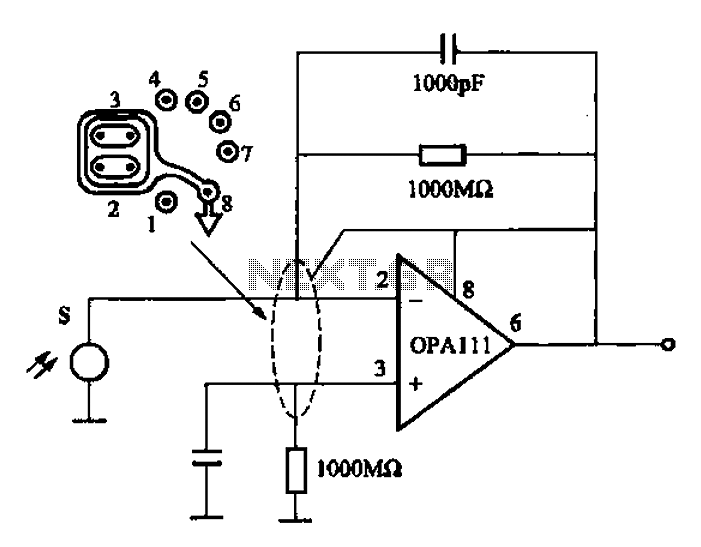
Infrared heat is emitted by an object during non-contact temperature measurement. The measured signal is weak, necessitating the use of highly sensitive thermal infrared sensors with minimal noise. Consequently, the amplifier circuit must also meet stringent requirements, as standard...
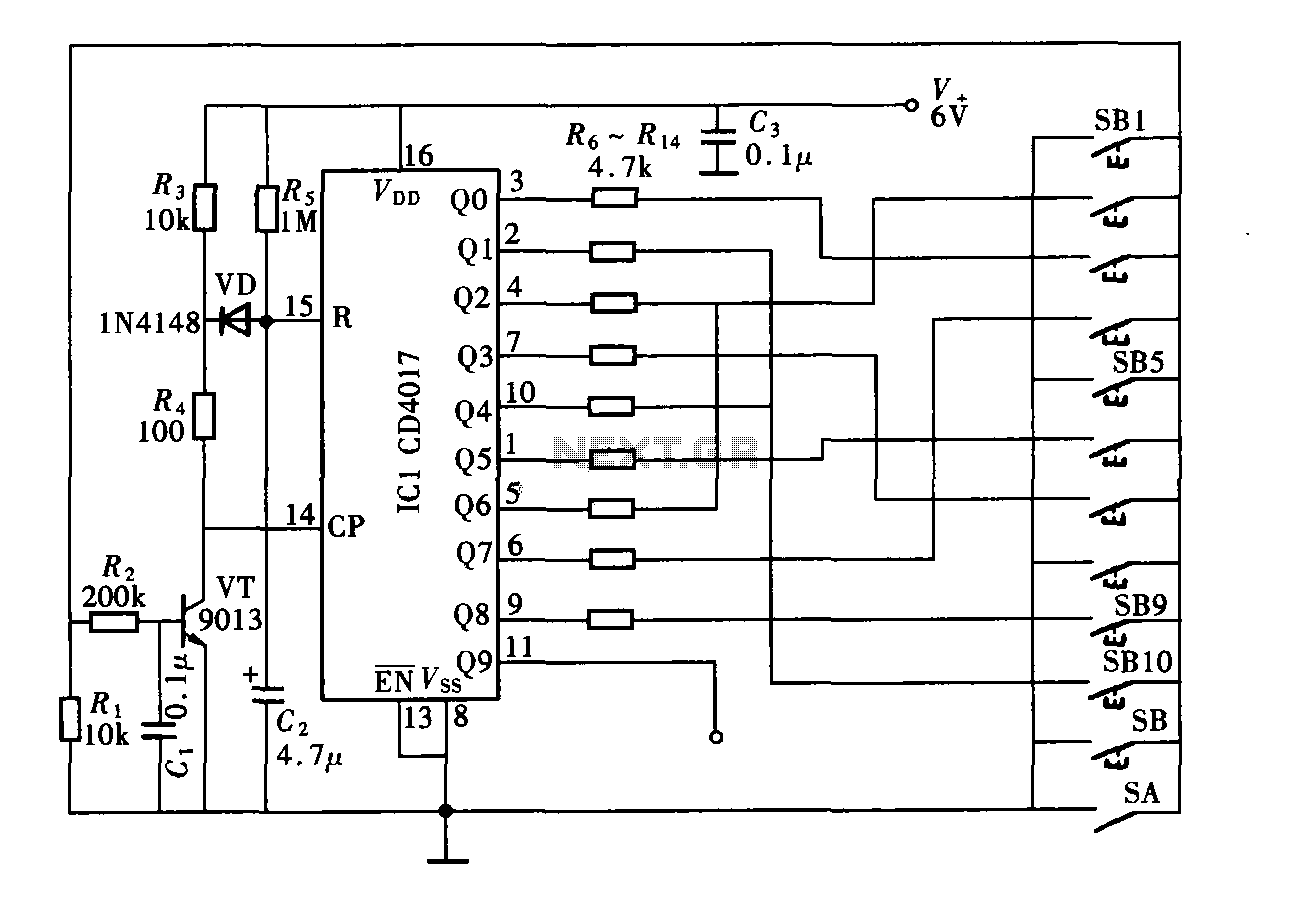
The digital controller features a nine-digit password system and includes a total of 11 keys. This comprises four pseudo-code keys and seven overlay keys, each of which has two valid key options. The total number of possible passwords is...

Any NPN transistor can be used. The author used a 2N3904, but a 2N2222A should work just as well. A good, low noise transistor would be even better. Some radios only have three connections to their ferrite bar antenna:...
This project is a cost-effective solution for operating 20 or 40-watt fluorescent tubes. The most efficient configuration utilizes a 40-watt tube or two 20-watt tubes connected in series. The circuit can be assembled using components sourced from a junk...

In this amplifier circuit, the gate of the MPF 102 is biased with an external voltage. This circuit achieves tighter control of the operating point and biasing conditions. The amplifier circuit utilizing the MPF 102 field-effect transistor (FET) is designed...