
400 Hz servo amplifier

The described circuit functions as a signal conditioning and control system designed to manage the operation of a servo motor. The initial signal, originating from either a synchro receiver or a potentiometer, is subjected to amplification by operational amplifier U1. The inclusion of Zener diodes D3 and D4 is critical, as they limit the output voltage swing to safe levels, preventing potential damage to downstream components.
Following amplification, the signal is routed to operational amplifiers U2 and U3. These amplifiers are configured to drive the gates of transistors Q1 and Q2, which are likely part of a switching mechanism controlling the power to the servo motor. The choice of using NPN and PNP transistors (Q3 and Q4) as current limiters is essential for protecting the MOSFETs MTM8N10 and MTM8P10 from overcurrent conditions, ensuring reliable operation.
Capacitors C3 and C4 play a crucial role in stabilizing the circuit by filtering out any DC offset that could affect the performance of the operational amplifiers and the transistors. This stabilization is vital for maintaining consistent operation, particularly in applications that require precision control, such as servo motor applications.
Finally, transformer T1 is employed to elevate the voltage to 120 V, which is necessary for the operation of the 400 Hz servo motor. This step-up transformer ensures that the motor receives adequate voltage for efficient performance, allowing for precise control in applications that demand high reliability and responsiveness. Overall, this circuit design reflects a well-thought-out approach to managing and amplifying signals for effective motor control in electronic applications.The signal from a synchro receiver or a variable resistive cam follower (potentiometer) is boosted by operational amplifier Ul, whose output swing is limited by back-to-back zeners D3 and D4. The signal is then applied to operational amplifiers U2 and U3, which drive the gates of Ql and Q2 respectively.
The npn transistor (Q3) is a fast current limiter for the n-channel MTM8N10; a pnp transistor (Q4) performs the same function for the p-channelMTM8P10. Capacitors C3 and C4 eliminate the need for accurate dc offset zeroing. T1 steps up the output voltage to 120 V for the 400 Hz servo motor.
Related Circuits
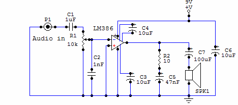
Here is a simple audio amplifier circuit that is easy to build and has few components. This circuit is built around the LM386 audio amplifier integrated circuit, useful when you need to power medium-sized speakers from a music player...
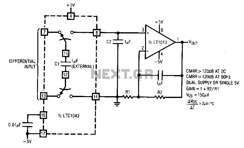
LTC1043 and LT1013 dual operational amplifiers are utilized to construct a dual instrumentation amplifier with only two packages. A single double-pole double-throw (DPDT) switch converts the differential input into a ground-referenced single-ended signal at the input of the LT1013....
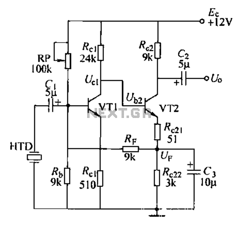
Dctl is a two-stage amplifier, with the first stage amplifying the collector voltage of transistor VT1. The second stage, represented by VT2, is proportional to the current flowing through the winding. The RF signal is applied to the sub-base...
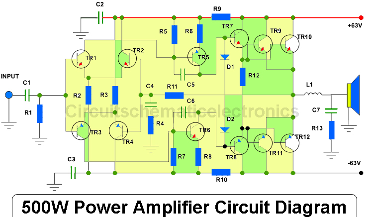
This amplifier has an output power of approximately 500 Watts, with a compatible voltage supply of up to 63 Volts. When operating, the output transistors should be mounted on an adequate heatsink due to the significant heat generated during...
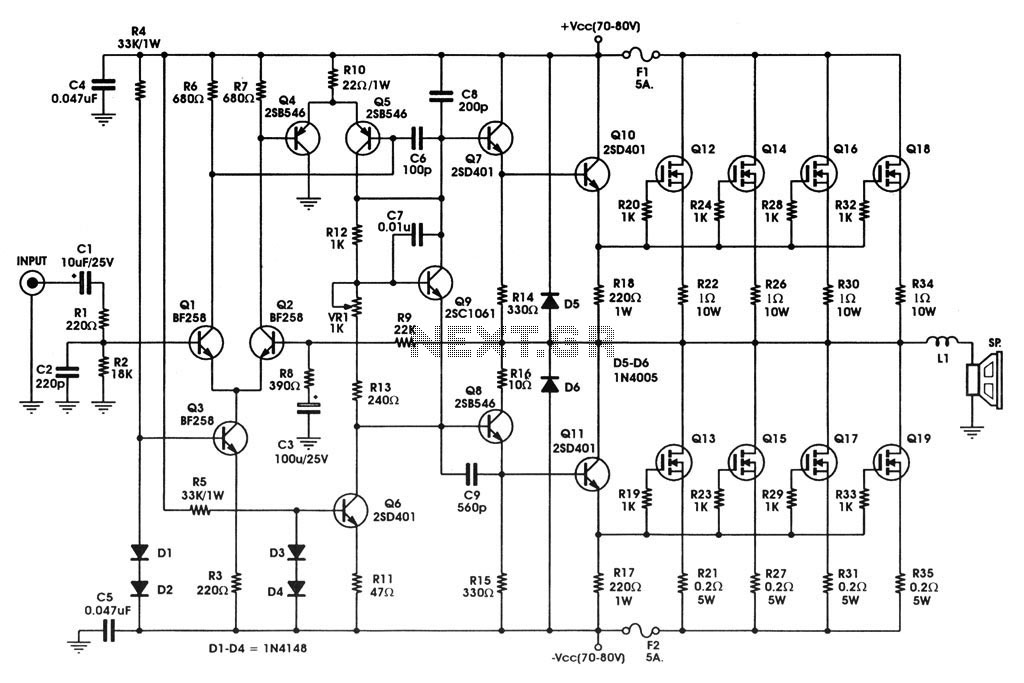
400 W MOSFET Audio Amplifier circuit using IRFP448. This circuit is categorized under amplifiers and includes five circuit diagrams. For more detailed information, refer to the main post titled "400 W MOSFET Audio Amplifier Using IRFP448." This post also...
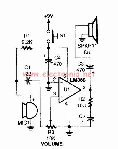
A voice amplifier can be designed using the LM386 power amplifier, which is intended for low voltage consumer applications. This simple circuit features variable gain and volume control. The gain is set internally to 20 to minimize the number...