
4011 For Protection Surge With Delay The Relay
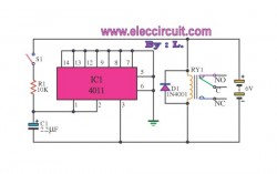
This circuit is designed to protect sensitive equipment from pressure-related damage while simultaneously managing the operation of additional appliances through a relay mechanism. The 4011 IC, a quad 2-input NAND gate, is utilized to process input signals and control the relay's operation.
The circuit may be configured to monitor pressure levels using a pressure sensor, which outputs a signal to the 4011 IC. When the pressure exceeds a predetermined threshold, the NAND gate logic can trigger the relay, disconnecting the load to prevent damage. The inclusion of a diode is critical as it protects the circuit from back EMF generated by the relay coil when it is de-energized, ensuring reliable operation and longevity of the components.
The delay function for the appliances is achieved through the timing characteristics of the circuit, which can be adjusted by incorporating resistors and capacitors in conjunction with the 4011 IC. This allows for a controlled delay before the relay reactivates the appliances, providing a buffer period that can help in managing sudden pressure changes or system recovery after an event.
Overall, this circuit serves dual purposes: safeguarding equipment from pressure-induced failure and enabling delayed operation of connected devices, thus enhancing the overall reliability and efficiency of the system.Function: To prevent equipment damage from pressure., and for delay other appliances connected to the output of the relay. 4011 IC, Diode, Relay, .. 🔗 External reference
Related Circuits
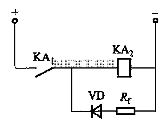
The circuit depicted in Figure 6-24 includes a relay coil with both ends connected in parallel to a resistor (Rf) or an auxiliary diode (VD). This configuration is intended to enhance power after a short circuit occurs in the...

This design outlines a power supply circuit capable of producing a 5V source voltage. The circuit is constructed using TTL integrated circuits (ICs) and features a simple design. In circuits utilizing TTL ICs, the supply voltage is critical, as...
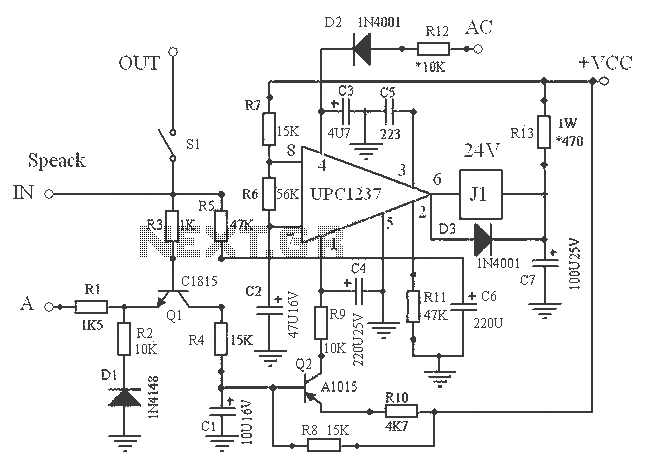
The uPC1237 operates with a single power supply, with an operating voltage range of 25V to 60V, typically used directly as a positive power source (+Vcc) for amplifiers. The relay coil voltage is 24V DC, and the relay driver...
Power supplies designed for use with TTL logic circuitry must protect against over-voltage, which can rapidly damage TTL chips. The duration of over-voltage that can harm TTL chips is too short to activate any conventional fuse, necessitating the use...
The 4 Channel Infrared (IR) Remote is a straightforward kit that utilizes the well-known HT12A and HT12D encoder/decoder chips from Holtek. The 4 Channel Infrared Remote system is designed for wireless communication, enabling remote control applications in various electronic devices....
The delay application circuit is depicted in Figure JEC-2, which consists of two components. When the input transitions from logic level 0 to 1, the output also changes to 1 immediately. However, when the input transitions from high level...