
5-12V 200mA Regulated Power supply
The circuit is designed to accept alternating current (AC) from 6V to 18V or direct current (DC) from 9V to 18V, with a maximum current rating of 1A. The input stage features a diode bridge rectifier, allowing for the conversion of AC to DC while ensuring polarity is not a concern, as the diodes can rectify current regardless of lead orientation. In instances where a DC plug pack is utilized, the diode bridge can be omitted, allowing for a direct connection to a 1,000μF electrolytic capacitor, which serves as a smoothing capacitor to stabilize the output voltage.
The 1,000μF electrolytic capacitor can handle currents up to 500mA. For applications requiring higher current, such as an 800mA or 1A plug pack, it is recommended to either replace the capacitor with a 2,200μF unit or add an additional 1,000μF capacitor in parallel. The circuit incorporates two indicator LEDs: a green LED indicating power status and a red LED that signals a dropout condition, illuminating when the output voltage falls below 3V, indicating an overload or short circuit condition.
The output voltage is adjustable, ranging from 5V to 9V or 12V, controlled by a 500Ω potentiometer. The board is marked with a scale to assist in setting the desired voltage. The voltage regulation is accomplished using a 7805 voltage regulator, which maintains a constant output of 5V above the ground reference. By elevating the ground reference, higher output voltages can be achieved.
Thermal management of the regulator is critical, as the heat generated is a function of the voltage drop across the regulator multiplied by the current. For instance, with an output of 12V and a current of 300mA, the power dissipation would be 0.9W. The supplied heat sink is rated for 3W, providing adequate thermal dissipation under normal operating conditions. However, at a lower output of 5V with the same current, the heat generated could reach 3W, necessitating careful monitoring to avoid thermal shutdown, which is indicated by the overload LED.
The assembly process involves securing the regulator to the board with a mini heat sink, followed by the installation of the potentiometer, diodes, electrolytic capacitors, and other components, ensuring correct orientation for polarized components such as LEDs and electrolytic capacitors. The output is connected via a 2-screw terminal block, allowing for flexibility in powering connected devices.
Overall, the design is compact and user-friendly, suitable for various applications requiring adjustable voltage regulation and current monitoring. It will accept AC from 6v to 18v or DC from 9v to 18v and any current up to 1 amp. The diode bridge on the input converts AC to DC and it doesn't matter which way around the leads are connected as the diodes compensate for either direction. If a DC plug pack is used, the bridge can be left out and the leads taken directly to the positive and negative of the 1,000u electrolytic.
If you use the bridge, no damage will result, however about 1.2v will be lost across it and this may reduce the output a little. The 1,000u electrolytic is suitable for currents up to 500mA and if you want to use an 800mA or 1 amp plug pack, you will have to replace it with a 2,200u or add another 1,000u.
The circuit contains 2 indicator LEDs. The green LED is POWER ON" and the red LED indicates "DROPOUT." This LED lets you know when you are drawing too much current or the output is shorted. It turns on when the output is less than 3v. The other feature of this circuit is the variable output voltage. It can be adjusted from 5v to 9v (or 12v) and the board contains a simple scale around the 500R pot so that the pointer on the shaft will indicate the approximate voltage. The regulator is a 7805 and this is a 5v type. The principle of operation of these 3-terminal devices is the output is always 5v higher than the "ground" lead.
Click HERE for a discussion on the 3-terminal regulator. If we "jack up" the ground lead, the output will rise also. This is how we get voltages higher than 5v. But there is one thing that's most important. It's heat-sinking the regulator. The heat generated by the regulator is a product of the voltage across it and the current flowing. As an example, at 300mA and 12v out, the voltage across the regulator will be at least 3v (3v is the minimum across the regulator to prevent it dropping out of regulation), making the heat generated about 3 x 0.3 = 0.9 watts (900mW). The heat-sink supplied in the kit is capable of dissipating 3 watts so we are below the maximum in this case.
But when the output is 5v and 300mA is flowing, the voltage across the regulator is 10v x 0.3A = 3 watts and the chip may start to heat up to a point where the thermal shut down feature will come into operation. When this happens, the chip starts to oscillate at a very high frequency in an attempt to reduce the current and allow the temperature to fall.
This only occurs when the chip is very hot and to give you a warning before it starts to occur, we have included an OVERLOAD LED. The overload circuit turns on when the output drops below 3v and this turns off a BC 547 transistor. This allows current to flow through the red LED. When the voltage rises again, the transistor turns on and the collector-emitter voltage is less than that required by the LED and it turns off.
In other words the transistor robs the LED of its 1.7v turn-on voltage. All the parts fit on a small PC board with the regulator screwed to a mini heat fin and the 500R pot fits on top of the board A scale is marked around the pot to correspond to a 12v plug pack and if you are using this type of pack, you have the output voltage ready-made. If you are going to mount the project in a box, you can use a 500R mini trim pot as a pre-set and have no external adjustment available, or mount a 500R pot on the outside of the box and duplicate the scale.
Our suggestion is to fit the board onto the front face of a plug pack with a piece of double-sided foam tape. This makes the whole unit very compact. Start assembly by fitting the leads of the regulator down its holes and screw it to the board with the mini "U" heat-fin between the regulator and the board.
The metal side of the regulator must touch the heat fin so that any heat generated by the regulator will be passed to the atmosphere. Next fit the 500R pot so that the three lead fit down the holes in the board as well as the two supporting tabs.
Next fit the 4 diodes so that they are touching the board, and solder them in position. Snip the leads close to the solder connection. Next is the 1,000u electrolytic. Make sure the negative lead is near the edge of the board. Bend the electro over so that it lays onto the board. Solder the leads and the electro will stay in position. Continue across the board with each component, noting that the two LEDs must be placed around the correct way. The cathode lead is the shorter one and the body of the LED has a flat next to the cathode. The transistor fits over the "D" on the board and the 100u electrolytic has the negative lead near the edge.
A 2-screw terminal block is the output of the project and you can use the lead cut from the plug pack as a flying lead to the project you are powering. The 100n capacitors must be mounted close to the leads of the regulator to prevent high frequency instability from occurring.
🔗 External reference
Related Circuits

This audio amplifier design utilizes TMOS Power FETs configured in a complementary common-source arrangement. The FETs are biased to cutoff and can rapidly turn on when a signal is applied. This design approach offers significant thermal stability in the...
This circuit is designed for individuals needing to boost or drop a voltage. The output operates at high frequency but can be rectified and filtered to provide a DC output. When rectifying high frequencies, it is essential to utilize...
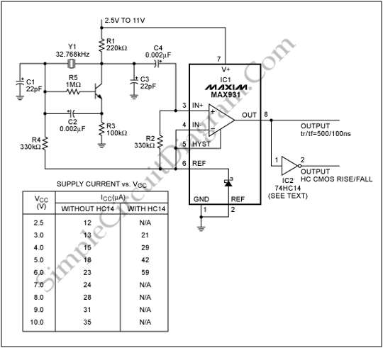
To generate a system clock or auxiliary sleep clock in microcontrollers (µCs) and low-power instruments, a 32 kHz oscillator is commonly utilized. This oscillator typically employs a CMOS inverter. A 32 kHz oscillator is essential for various timing functions in...
The Electronics Schematic Diagram MJR7-Mk3 Mosfet MJR6 page includes distortion extracted using the nulling method with a speaker load and a music signal to demonstrate that these designs have no audible distortion in normal use. The MJR7 has even...
COMSOL's integration of SPICE® elements into its finite element method (FEM) allows for direct modeling of oscillators. In this approach, the triode and load are described using FEM, while all other circuit components are simulated with SPICE®. This modeling...
This discussion assists in selecting the most appropriate microprocessor supervisor integrated circuit (IC) for specific applications and provides solutions for various common supervisory issues encountered with microprocessors. Microprocessor supervisor ICs are critical components in ensuring the reliable operation of microprocessor-based...