
mjr7 mk3 mosfet audio power amplifier 70w
The MJR7-Mk3 Mosfet amplifier circuit is designed to minimize distortion while maintaining high fidelity audio performance. The implementation of the nulling method for distortion extraction ensures that the amplifier operates without audible distortion during normal usage, which is critical for high-quality audio applications. The enhancements introduced in the MJR7 design, including the addition of a 220uF capacitor and the use of diodes and resistors to control the switch-on characteristics, reflect a thoughtful approach to maintaining compatibility with sensitive speaker systems.
The circuit's design philosophy emphasizes the importance of managing transient outputs, particularly during start-up and shut-down phases, to protect delicate high-frequency drivers. The reduction of the output pulse from 4V to 1V at switch-on significantly mitigates any perceptible thump, enhancing the overall user experience.
In terms of component selection, the potential for substituting transistors with alternatives from Toshiba indicates a proactive approach to sourcing reliable components. The decision to modify certain resistor values for better availability without compromising performance demonstrates an understanding of practical engineering constraints.
The consideration of voltage ratings for capacitors and the implications of increasing supply voltage highlight the design's flexibility and focus on safety under various operating conditions. The discussion on power levels and perceived loudness reinforces the notion that higher power does not always equate to better sound quality, aligning with the amplifier's objective of delivering a refined audio experience.
Overall, the MJR7-Mk3 Mosfet amplifier circuit exemplifies a well-balanced design that prioritizes audio fidelity, user safety, and practical component management while being adaptable for various audio applications.The Electronics Schematic Diagram MJR7-Mk3 Mosfet MJR6 page includes distortion extracted using the nulling method with a speaker load and a music signal to demonstrate that these designs have no audible distortion in normal use. The MJR7 has even lower distortion, for example the 19kHz + 20kHz intermodulation product at 1kHz is about 19dB lower.
I have a new improved board layout, and may make boards available soon. Now there is an additional 220uF capacitor plus two diodes and a resistor which slow down the switch-on to keep the output pulse low enough for use with most high sensitivity speakers. For use in a bi-amp or tri-amp system with active crossover filters the pulse also needs to be small so that direct driven high frequency drive units are not damaged.
The circuit addition is a simplified version of an idea suggested to me a few years ago. With the modification added the switch-on thump becomes almost inaudible. With the original MJR6 the output pulse was 4V peak, this has now been reduced to 1V. There is no audible thump at switch-off. I would prefer to leave out the 12V gate protection zeners, but I doubt whether the mosfet internal zeners have adequate current rating. With a negative output into a low impedance or shorted output the zener current would only be limited by the 300R gate resistor, which is why the zeners are placed after the resistors, and relatively high 300R values are used.
There are possible alternative, but so far untried, input stage transistors, the Toshiba 2SA970BL and 2SC2240BL, which appear to be good substitutes for the Hitachi 2SA1085E and 2SC2547E. The BL` suffix is the high gain group. Alternatives for the Sanyo 2SC2911 and 2SA1209 are the Toshiba 2SC3423 and 2SA1360, which again are untried.
Based entirely on my own experience Toshiba devices are more likely to be faked, maybe this is because they are more popular so more attractive to substitute remarked cheaper devices, or maybe I have just been unlucky with these. Some of the component values have been changed (29 Jan 2009). This is to ensure easier availability, for example a 7R5 resistor has become 6R8 because I wanted to use a 3watt component, which is not so easy to find in the old value.
The 470uF and 220uF could be rated at 100V to enable use of a higher supply voltage. Increasing the 4400uF (2 x 2200uF) to 100V would then be a good idea although it normally operates at half the supply, to ensure safety under fault conditions or when adjusting the output voltage. Increasing the supply close to 100V the average sinewave power into 8ohms increases from 30W to over 80W.
Before deciding on the higher power option I suggest checking carefully what output level is really needed before worrying too much about power rating. There are many people happily using 5 or 10 watt class-A amplifiers who feel no need for more power. Remember the logarithmic loudness effect, doubling the power is nowhere near a doubling of percieved loudness, and the difference between 30W and 80W is not as dramatic as we might expect.
I wrote a piece about the problems of high power, which include thermal compression, while high sound levels can cause both temporary and permanent hearing loss. The temporary effect can be a raising of the threshold of hearing by as much as 40dB, so using high levels in order to achieve a high dynamic range` could have the opposite effect.
The MJR7 is designed for quality rather than quantity, and if much higher power is really needed there are other more suitable design approaches. 🔗 External reference
Related Circuits
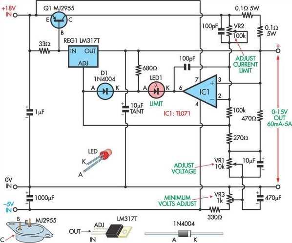
This circuit, based on a National Semiconductor application note, utilizes an LM317 3-terminal regulator (REG1) due to its integrated over-current and over-temperature protection features. The output current is amplified to slightly over 5A using the MJ2955 transistor (Q1). The...
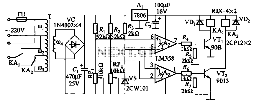
It utilizes two LM358 operational amplifiers, A2 and Ar, to create a voltage measurement comparison control circuit for upper and lower limit voltage settings. The circuit includes a Raspberry Pi adjustment potentiometer (RPi) and an additional potentiometer (RP2) to...
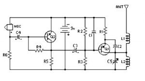
4 Stage FM Transmitter. This FM transmitter circuit utilizes four radio frequency stages, functioning as a VHF oscillator. It is available for wholesale through fmuser, including the CZE and CZH models of FM transmitters, which are suitable for OEM...
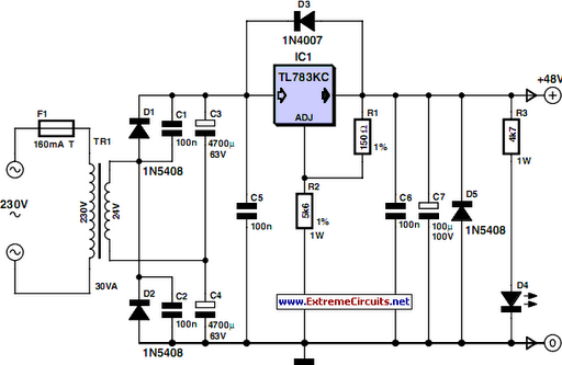
48 V phantom powering has become the standard for professional condenser microphones. The supply voltage is applied over both wires of the balanced screened cable via two 6.8 kΩ resistors. The absolute value is not critical, as a variation...
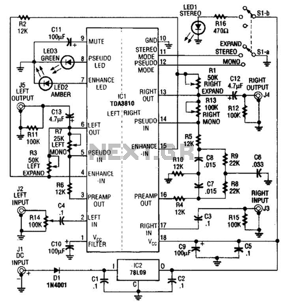
This audio processor utilizes the Signetics/Philips TDA3810N stereo, spatial, pseudo-stereo processor integrated circuit (IC). The processor employs the Philips TDA3810IC device and operates as an expander, pseudo-stereo processor, and audio enhancer. Pseudo-stereo is achieved by directing different frequencies to...
A typical circuit for applications such as mobile phones, MP3 players, and portable electronics utilizing the SSM2602 Low Power Audio Codec is provided in the SSM2602 Applications Circuit Schematic. The SSM2602 Low Power Audio Codec is designed for high-performance audio...
Warning: include(partials/cookie-banner.php): Failed to open stream: Permission denied in /var/www/html/nextgr/view-circuit.php on line 713
Warning: include(): Failed opening 'partials/cookie-banner.php' for inclusion (include_path='.:/usr/share/php') in /var/www/html/nextgr/view-circuit.php on line 713