
5 Zone Alarm System
Zone 1 is a timed zone which must be used as the entry and exit point of the building. Zones 2-5 are immediate zones, which will trigger the alarm with no delay. Some RF immunity is provided for long wiring runs by the input capacitors, C1-C5. C7 and R14 also form a transient suppressor. The key switch acts as the Set/Unset and Reset switch. For good security, this should be the metal type with a key. At switch on, C6 will charge via R11; this acts as the exit delay and is set to around 30 seconds. This can be altered by varying either C6 or R11. Once the timing period has elapsed, LED6 will light, meaning the system is armed. LED6 may be mounted externally.
The alarm system utilizes three CMOS integrated circuits (ICs) to manage the various functions of the system effectively. The first IC handles the input processing for the zones, where each zone's normally closed contact is connected. When a switch is activated (opened), it triggers the alarm condition for immediate zones 2 to 5, while zone 1 provides a grace period for entry or exit.
The second CMOS IC manages the timing functions, particularly for the entry/exit delay. The timing capacitor C6 and resistor R11 form an RC timing circuit that dictates the delay duration. Adjustments to R11 or C6 allow for customization of the exit delay, providing flexibility based on user needs. Once the delay expires, the system transitions to armed mode, indicated by the illumination of LED6.
The third CMOS IC is responsible for the alarm sounding mechanism and the panic button functionality. When triggered, it activates the alarm sounder, providing audible notification of the breach. The panic button, when pressed, will immediately trigger the alarm regardless of the system's state, ensuring user safety in emergency situations.
The design incorporates input capacitors C1 to C5 to mitigate RF interference, which can be particularly useful in installations with long wire runs, helping to maintain system stability and reliability. The transient suppressor formed by C7 and R14 protects the circuit from voltage spikes, enhancing the longevity of the components.
Overall, this alarm system is designed with user security and convenience in mind, providing reliable monitoring of multiple zones while allowing for easy customization and installation within a residential or small office environment.This is a complete alarm system with 5 independent zones suitable for a small office or home environment. It uses just 3 CMOS IC`s and features a timed entry / exit zone, 4 immediate zones and a panic button.
There are indicators for each zone a "system armed" indicator. Each zone uses a normally closed contact. These can be micro switches or standard alarm contacts (usually reed switches). Suitable switches can be bought from alarm shops and concealed in door frames, or window ledges. Zone 1 is a timed zone which must be used as the entry and exit point of the building. Zones 2 - 5 are immediate zones, which will trigger the alarm with no delay. Some RF immunity is provided for long wiring runs by the input capacitors, C1-C5. C7 and R14 also form a transient suppresser. The key switch acts as the Set/Unset and Reset switch. For good security this should be the metal type with a key. At switch on, C6 will charge via R11, this acts as the exit delay and is set to around 30 seconds. This can be altered by varying either C6 or R11. Once the timing period has elapsed, LED6 will light, meaning the system is armed. LED6 may be mounted exter 🔗 External reference
Related Circuits
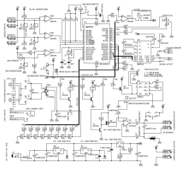
A low-cost, high-performance programmable home security system utilizing a few LDRs as input sensors. When the sensors are triggered, the system can dial a user-specified phone number using a built-in DTMF generator and activate a high-power audio alarm and...
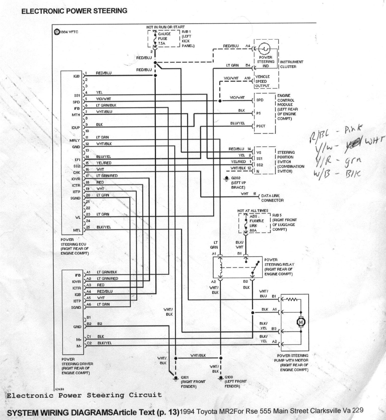
The goal was to control the MR2 power steering pump to reduce noise and power consumption, as it operates at full throttle continuously. Designing a custom motor controller was not feasible due to a lack of expertise, and off-the-shelf...

In a panic situation during the night when an intruder attempts to break into a house, this alarm system will assist by emitting a loud police siren to deter the intruder. The alarm system is designed to enhance home security...
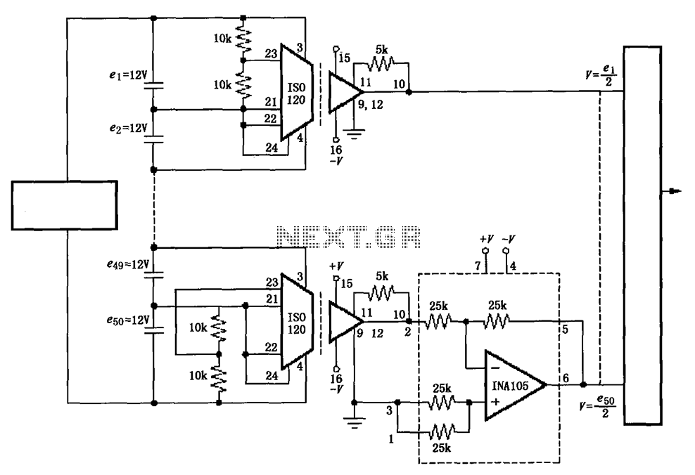
The circuit utilizes the ISO120 and INA105 instrumentation amplifiers to create a battery monitoring system for a 600V battery setup composed of 50 series-connected 12V batteries. This circuit is designed to detect charging and discharging conditions to prevent overcharging...
A project for a morning or sunrise alarm circuit that generates a beep-beep alarm sound and flashes an LED in response to sunlight. This sunrise alarm circuit is designed to provide a gentle awakening experience by utilizing both auditory and...
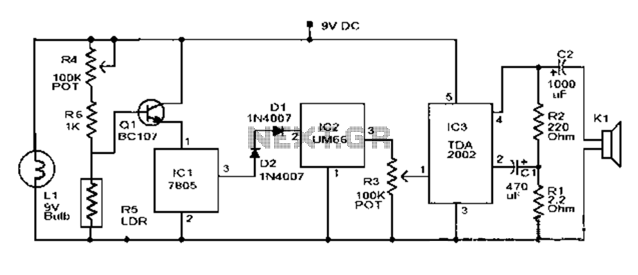
This document outlines a basic fire alarm circuit utilizing an LDR (Light Dependent Resistor) for fire detection. The circuit is designed to generate an audible alarm in response to smoke, which affects the LDR's resistance. In the absence of...
Warning: include(partials/cookie-banner.php): Failed to open stream: Permission denied in /var/www/html/nextgr/view-circuit.php on line 713
Warning: include(): Failed opening 'partials/cookie-banner.php' for inclusion (include_path='.:/usr/share/php') in /var/www/html/nextgr/view-circuit.php on line 713