
Toyota MR2 Power Steering System

The MR2 power steering pump control system integrates several components and sensors to optimize performance while reducing energy consumption and noise. The original MR2 motor controller is central to this design, featuring an automatic shut-off function that halts the hydraulic pump when steering input is absent or the vehicle is stationary. This feature significantly enhances efficiency by preventing unnecessary power draw.
The system utilizes a Zilla contactor to engage the power steering only when required. The engagement of the contactor activates the original MR2 controller, which in turn powers the hydraulic pump. The integration of the steering wheel sensor allows the controller to adjust the pump's output based on the driver's steering input, providing responsive steering assistance. The road speed information from the cruise control sensor is critical for limiting the pump's output at higher speeds, thereby preventing oversteering and enhancing vehicle stability.
The monitoring of the hydraulic pump's operational status is achieved through built-in sensors that detect brush wear and overheating conditions, allowing for timely maintenance and ensuring the longevity of the pump. The power steering schematics from the 1994 and 1995 MR2 models provide a reliable reference for wiring and component selection, ensuring compatibility and functionality.
In implementing this control system, careful attention was paid to the ICT (PSCT) control wire, which interfaces with the main engine ECU. This wire must be grounded to disable the power steering ECU when the engine is not running. The use of a micro relay and a resistor ensures that the wire remains grounded until the main contactor is engaged, allowing for seamless operation of the power steering system.
Overall, this comprehensive approach to controlling the MR2 power steering pump effectively balances performance, efficiency, and reliability, making it a valuable enhancement for vehicle systems.Wondered how to control the MR2 Power steering pump so that it is not a noisy power hog because it ’s always on full throttle. Designing some sort of motor controller or using a small off-the-shelf controller would not work for me.
One, I ’m not that great of a designer of controllers (I ’ll leave this up to Otmar). Second, a small of f-the-shelf controller would not work on high voltage systems. Plus, I would have to program some type of Micro or Basic Stamp to get all the functions I want. So I decided to get the original motor controller from a MR2 at the junk yard and try to wire it up. Well, it works better than I anticipated. One of the modes of the MR2 controller is to slow the hydraulic pump to a stop when there is no movement of the steering wheel or vehicle road speed: saves power! I have also wired it to enable itself when the Zilla Contactor is engaged. I`m using the original steering wheel sensor from the MR2, so it senses how much steering I`m applying.
It is also getting road speed info from the cruise control speed sensor to limit over-steer at high road speeds. It uses the sensors in the pump to tell you when the brushes are worn or overheated. The P. S. schematics provided are from a ’94 and ‘95 MR2, so try and get all the parts from a Toyota close as possible to these years.
There are a couple different versions of the schematics here, so use the one that best suits your needs. 1. I used the original cruise control speed sensor for my ’85 S10 to drive the ECU and it has worked with good results.
Your results or pulse rates may vary. 2. The ICT (PSCT) is a control wire for the main engine ECU to enable the P. S. when the engine is running. The P. S. ECU is disabled when this wire is brought low (grounded). So I used a micro-sized relay and a 1K Ohm resister to keep this wire low until the main contactor is engaged. I hooked the small relay in parallel with main contactor. My Zilla has no problem with this. 3. My Hydraulic pump was from a slightly different year so it had only 3 sensor wires. After some testing I realized that it was missing the V-L or Violet/Light Stripe wire. Look at the schematic and you will see how easy this was fixed. 🔗 External reference
Related Circuits
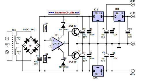
Inexpensive miniature transformers typically offer one or two secondary voltages, which are adequate for producing a set of positive and negative supply voltages. Miniature transformers are compact devices commonly utilized in various electronic applications, particularly in power supply circuits. These...
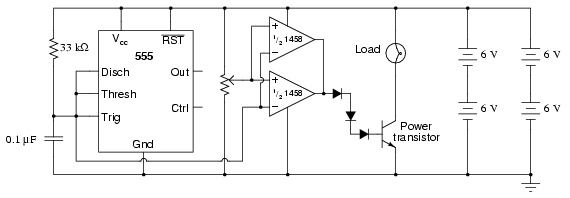
This circuit utilizes a 555 timer to generate a sawtooth voltage waveform across a capacitor, which is then compared to a steady voltage provided by a potentiometer using an operational amplifier (op-amp) configured as a comparator. The comparison of...

This is a 1-amp variable-voltage power supply unit (PSU) that can adjust output voltage from approximately 3V to 24V. It features a maximum output current limit, which is particularly useful when powering up a project for the first time...
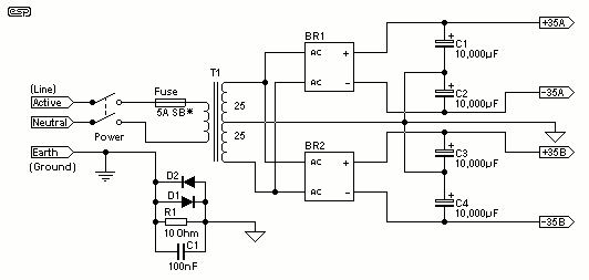
For the 60W amplifier, a nominal (full load) supply of +/- 35V is required, so a 25-0-25 secondary is ideal - however, see Updates, below. The circuit for the supply is shown below, and uses separate rectifiers, capacitors and...
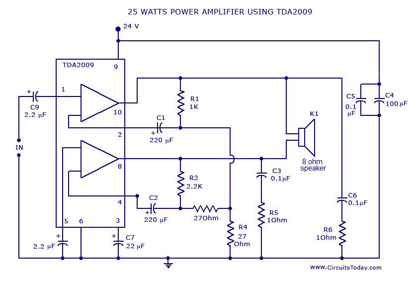
Power amplifier circuit diagram with schematics. This simple audio power amplifier circuit is designed for 25 watts output power using TDA 2009 IC, which has two channels (stereo), 12.5 W for each channel. The described power amplifier circuit utilizes the...
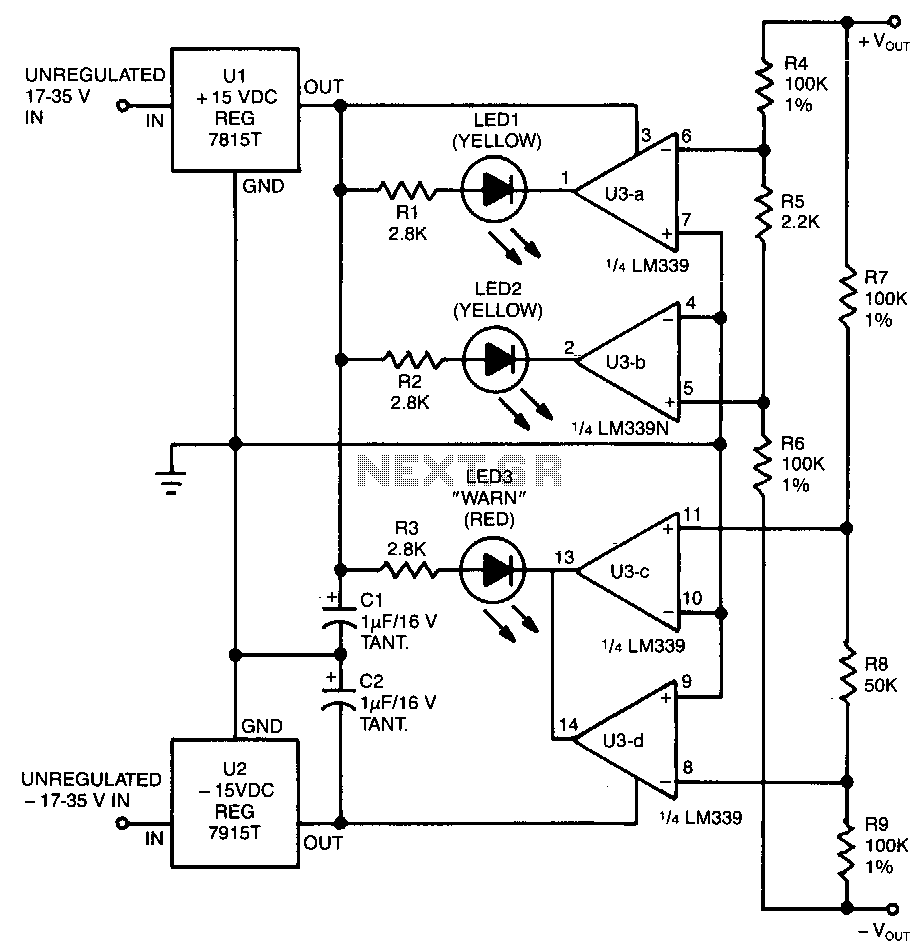
This circuit utilizes two pairs of comparators from an LM339N quad comparator. One pair controls the yellow positive (+) and negative (-) indicators, while the other pair drives the red warning LED3. The circuit is powered by the unregulated...