
50hz accurate oscillator circuit

The ELM446 integrated circuit is designed to function as a digital frequency divider, specifically tailored for applications requiring precise timing signals derived from a stable oscillator. The circuit operates by utilizing a 3.58MHz crystal oscillator, which is a common frequency for NTSC television systems. This frequency serves as the source from which the ELM446 generates two key output frequencies: 50Hz and 1Hz.
To implement the ELM446 in a circuit, the designer must connect a 3.58MHz crystal to the designated oscillator pins of the IC. Alongside the crystal, two loading capacitors must be connected to ensure the oscillator operates at the correct frequency. It is essential to choose capacitors with appropriate values to match the specifications of the crystal being used, as this will impact the stability and accuracy of the output signals.
The ELM446 features internal circuitry that precisely divides the input frequency to yield a stable 50Hz output. This output is particularly useful in applications requiring synchronization with standard power line frequencies. Additionally, the circuit provides a complementary 50Hz signal, which is beneficial for applications needing a phase-inverted version of the original signal.
Furthermore, the 50Hz output can be divided further within the IC to produce a 1Hz output. This division is accomplished through the internal logic of the ELM446, allowing for straightforward integration into timing applications, such as clock generation or event timing in microcontroller systems.
For power supply considerations, it is critical to provide a bypassed power supply to the ELM446 to minimize noise and ensure stable operation. Proper decoupling capacitors should be placed close to the power supply pins of the IC to filter out any high-frequency noise that may affect the performance of the oscillator.
In summary, the ELM446 is a versatile and efficient digital divider IC that simplifies the generation of low-frequency timing signals from a high-frequency crystal oscillator. Its design allows for easy integration into various electronic systems requiring reliable frequency division and timing control.The IC ELM446 is an 8 pin digital divider integrated circuit, that provides both 50Hz and 1Hz outputs from a common 3. 58MHz NTSC colourburst crystal. Externally, the designer need only provide the crystal and two appropriate loading capacitors, as well as a suitably bypassed power supply.
Internal Oscillator circuits then use this reference freque ncy to precisely derive a stable 50Hz signal. For convenience, a complementary 50Hz signal is also provided. This signal is then further divided to provide a 1Hz signal output. By ELM Electronics 🔗 External reference
Related Circuits
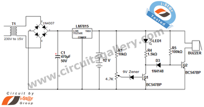
This is a straightforward 12V rechargeable smart battery charger circuit. It can be utilized as a charger for car batteries, inverter batteries, emergency light batteries, and more. An automatic indicator alarm circuit accompanies this battery charger schematic. The primary...
This circuit generates audio musical notes that can be heard from a distance of up to 10 meters. It consists of two main components: an infrared (IR) music transmitter and an IR music receiver. The IR music transmitter operates...
LCD modules have become a popular means of displaying system messages and status in embedded applications. This application note demonstrates how to interface an SST FlashFlex microcontroller to a typical character LCD module. The SST FlashFlex is an industry-standard,...
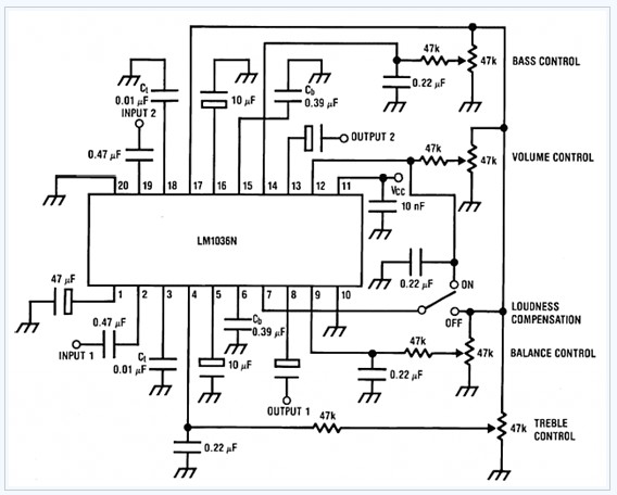
The LM1036 is a DC-controlled tone (bass/treble), volume, and balance circuit designed for stereo applications in car radios, televisions, and audio systems. It features an additional control input that facilitates loudness compensation. Four control inputs enable the adjustment of...
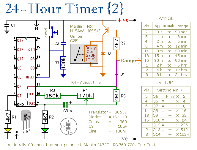
These two circuits are multi-range timers that offer periods of up to 24 hours and beyond. They can function as repeating timers or single-shot timers. Both circuits are fundamentally the same, with the primary distinction being their behavior in...

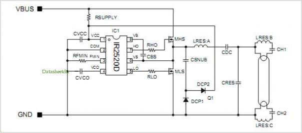
This is a design circuit for a low distortion crystal oscillator. The circuit generates a sine wave with low phase noise and distortion, allowing for the use of a crystal with less than 1mV dissipated across it. The crystal...