
50mhz 300w mosfet amplifier circuit

An RF power amplifier is a critical component in various communication systems, serving to enhance the power level of radio frequency signals for effective transmission. The design of an RF power amplifier involves several key parameters that must be optimized to ensure performance and reliability.
Firstly, efficiency is paramount; it is defined as the ratio of output power to input power. High efficiency minimizes heat generation, which is crucial for maintaining performance and prolonging the lifespan of the amplifier. The output power, often expressed in terms of P1dB, is the power level at which the amplifier begins to compress the output signal. This parameter is essential for understanding the amplifier's linearity and overall performance under varying load conditions.
Gain is another critical factor, representing the ratio of output signal power to input signal power. A good gain ensures that the amplifier can effectively boost weak signals to usable levels without introducing excessive noise. Return loss on both input and output is also significant; it measures how well the amplifier matches the impedance of connected components, impacting signal integrity and minimizing reflections that can degrade performance.
Heat dissipation is a design consideration that directly affects both the efficiency and reliability of the amplifier. Effective thermal management strategies, such as heat sinks and thermal pads, are often incorporated to dissipate heat generated during operation.
RF power amplifiers find applications in various fields, including telecommunications, broadcasting, and industrial heating. In telecommunications, they are vital for driving antennas that transmit signals over long distances, ensuring that the signal maintains its integrity and strength. In microwave heating applications, RF power amplifiers are utilized to generate heat for processes such as cooking or material processing. Additionally, they play a role in exciting resonant cavity structures, which are essential in various scientific and industrial applications.
Overall, the design and application of RF power amplifiers are crucial for enhancing the performance of radio frequency systems, ensuring that signals are transmitted efficiently and effectively across various platforms.An RF power amplifier is a type of electronic amplifier which is utilised to convert a low-power radio-frequency signal into a larger signal of significant power, usually for driving the antenna of a transmitter. It is usually optimized to have high efficiency, high output Power (P1dB) compression, good gain, good return loss on the input and outp
ut, and optimum heat dissipation. The basic applications of the RF power amplifier include driving to another high power source, driving a transmitting antenna, microwave heating, and exciting resonant cavity structures. Among these applications, driving transmitter antennas is most well known. 🔗 External reference
Related Circuits
Temperature indicators and temperature-based products have garnered significant interest due to their numerous applications and various possible solutions, each presenting unique advantages and disadvantages. This concept focuses on a sensor interface that delivers high accuracy while minimizing board space....
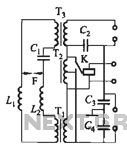
Tubular xenon lamp power, high brightness, known as the "little sun." Tubular xenon lamp wiring is illustrated in Figure 2-6. The tubular xenon lamp is a high-intensity discharge (HID) light source, characterized by its ability to produce a bright white...
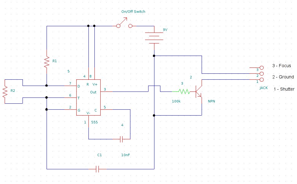
This document provides information on constructing a DIY time-lapse circuit that enables a camera to automatically capture images at specified time intervals. These images can then be compiled to create a time-lapse film. The circuit utilizes a 2.5 mm...
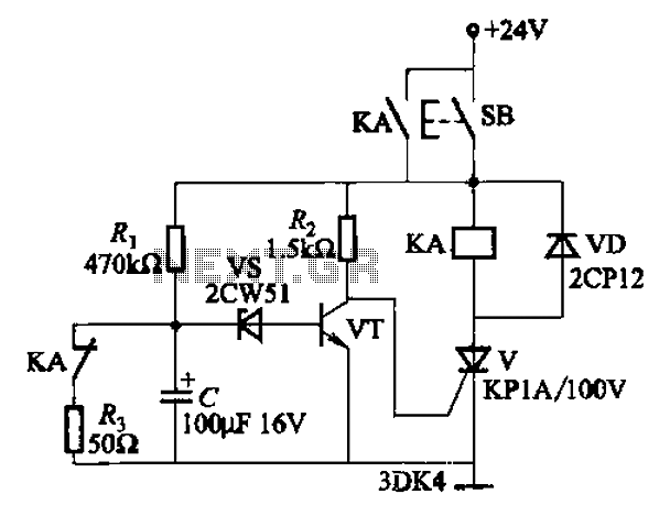
This circuit is a thyristor-based delay circuit known as a cut-off delay. It allows for a specified delay period after the thyristor is activated. The delay time of the circuit can be adjusted within 10 seconds by changing the...
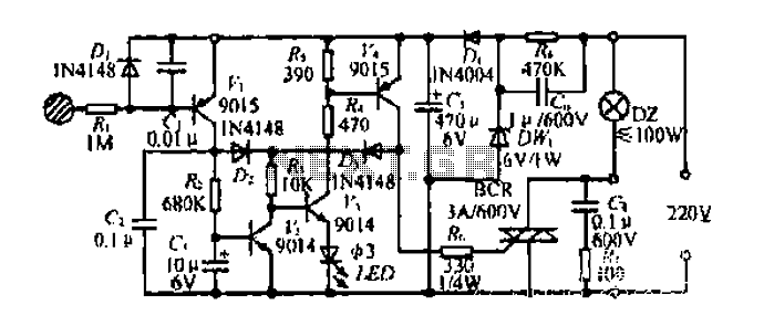
Diagram 2 depicts a shake tube circuit with a capacitance (C) and a trigger voltage rectifier filter element. The circuit includes a trigger voltage transistor amplifier (H), three pull tubes (n, U, v), and utilizes a thyristor as a...
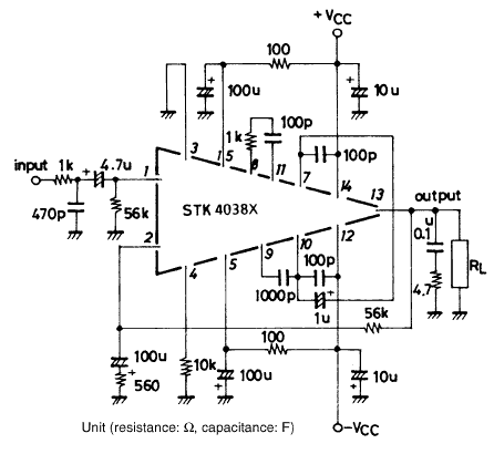
Using the STK4038X audio amplifier IC, can be designed a very simple high power and efficiency audio power amplifier. This circuit is manufactured by Sanyo Corporation and will provide an output power of 60 watts on an 8 ohms...
Warning: include(partials/cookie-banner.php): Failed to open stream: Permission denied in /var/www/html/nextgr/view-circuit.php on line 713
Warning: include(): Failed opening 'partials/cookie-banner.php' for inclusion (include_path='.:/usr/share/php') in /var/www/html/nextgr/view-circuit.php on line 713