
A touch-AC electronic switching circuit
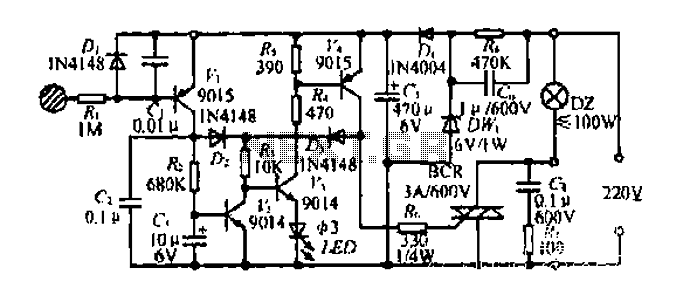
The circuit described operates as a touch-sensitive switch utilizing both capacitive sensing and transistor amplification. The initial touch triggers the rectification of AC voltage induced by the human body, which is then filtered to produce a usable DC voltage. The transistor amplifier (H) plays a crucial role in amplifying the input signal, allowing for reliable triggering of subsequent components.
The two paths for the electrode current serve to control the state of the transistors in a manner that is responsive to the duration of the touch. The design ensures that a brief touch does not significantly impact the capacitor's voltage, preventing unwanted triggering of the thyristor. In contrast, a prolonged touch allows for sufficient current to flow through the charging resistor (Rz), enabling the capacitor (C3) to reach the threshold voltage necessary to deactivate the transistor (n) and thus the thyristor (BCR), resulting in the light bulb (DZ) turning off.
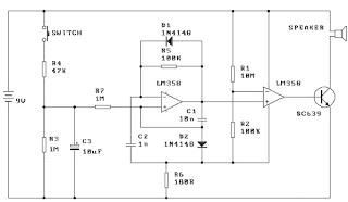
The use of a thyristor as a BCR diac in this circuit is particularly effective for controlling high-power loads, as it can handle significant currents while remaining in a stable state once triggered. The LED indicator provides visual feedback on the operational status of the circuit, enhancing user interaction. Overall, this circuit design illustrates an efficient method of interfacing human touch with electronic control systems, suitable for applications in automation and remote control.Diagram 2 shake tube n. Capacitance C. Trigger voltage rectifier filter element. H is a trigger voltage transistor amplifier circuit, three pull tube n, U, v. Composition trigg er thyristor as BCR diac. LED switching status display, c6. G. day. DW, dish for the power circuit section. When touched with a finger briefly under speculation inch touch sheet, the bodys AC induction voltage through the diode rectifier, capacitor c, filter plus obtain a pulsating DC voltage, input A transistor base so conduction, H set an electrode current two routes, all the way to the flow of R.V2 base because it is a short touch, so collector current is short, the current does not cause C, the voltage changed greatly .K not turned on, and the other JL! stream troops, R, U G pole, so n will have collector current flowing through the n base, so n.V4 from off state into saturated conduction state exhausted, the n-nest high electrode electrically him (nearly 6V supply voltage).
the a current through the SCR system very romantic person, SCR BCR conducting open shoulder .DZ light bulb. and when the high potential electrode V-ju, will maintain the current through the island, K3 inflows U base, maintain U.
the V4 saturated conduction state. to turn off power to the switch, just simply touching a finger again to bring films, Rang contact time is more than 3 seconds, so collector electrode has a longer duration of current flows through Rz charge to C3, when the white charging to 0.7V, n is turned off and the n low potential, V4 also turned off thyristor gate current losing BCR cut LL.DZ lamp goes out. after touch-up, U, V held in the off state.
Related Circuits
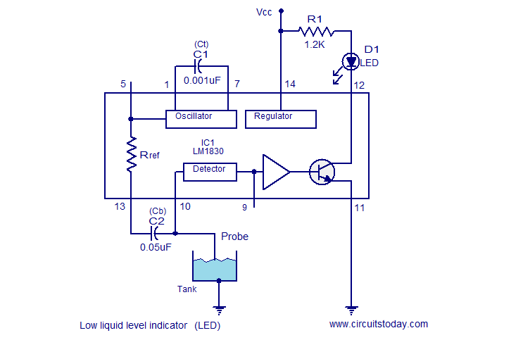
The following circuit illustrates a Liquid Level Sensor Indicator Circuit utilizing the LM1830 integrated circuit. Features: Manufactured by National Semiconductors, the device... The Liquid Level Sensor Indicator Circuit employing the LM1830 IC is designed to detect and indicate the level...
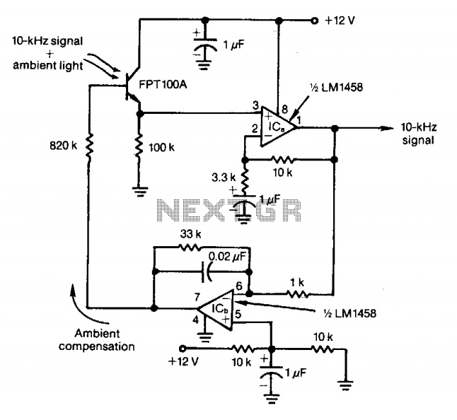
The feedback control of the phototransistor in this optical detector helps negate the effects of varying ambient light sources. The output of a modulated visible-light LED is detected, amplified, buffered, and fed through a low-pass filter. Ambient light signals...
The Electronic Cash Register (ECR) keeps track of sales transactions quickly and effectively. An abundance of PLUs (Price Look Ups) and department keys accommodate a variety of merchandise items. This means a faster, more accurate check out process and...
When the switch is pressed, capacitor C3 charges through resistor R4 with a time constant of 0.47 seconds. Upon releasing the switch, C3 discharges more slowly through resistors R7 and R3, with a time constant of approximately 5 seconds....
A battery voltage indication circuit that changes the status display. When the battery voltage is normal, an additional transistor drives an LED, which remains off. However, if the battery voltage falls below a critical threshold, the LED begins to...
The integrated circuit LM386 is a low-power audio frequency amplifier that requires a low-level power supply, typically batteries. It is available in an 8-pin mini-DIP package. The IC is designed to provide a voltage amplification of 20 without the...
Warning: include(partials/cookie-banner.php): Failed to open stream: Permission denied in /var/www/html/nextgr/view-circuit.php on line 713
Warning: include(): Failed opening 'partials/cookie-banner.php' for inclusion (include_path='.:/usr/share/php') in /var/www/html/nextgr/view-circuit.php on line 713