
50W Tube-Valve SW transmitter
The antenna system should have a feed impedance of 75 ohms, with two horizontal sections of the antenna measuring 10 meters each for operation at 6 MHz, reducing to 3.5 meters for operation at 22 MHz. Coordination of the rotation of capacitors C2, C3, and C4 is essential to minimize the current reading on the ammeter, which indicates optimal power radiation.
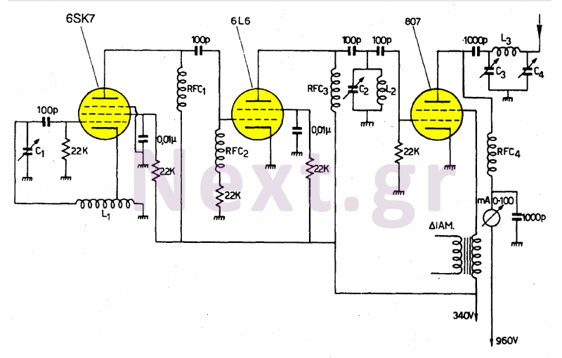
This transmitter circuit is designed to efficiently generate shortwave signals within the specified frequency range. The use of a 6SA7 tube in conjunction with precisely wound coils and variable capacitors allows for fine-tuning of the oscillation frequency. The variable capacitors (C1, C2, C3, and C4) play a critical role in adjusting the resonant frequency of the circuit, allowing for effective signal transmission.
The construction of the coils is crucial; the dimensions and wire gauge directly influence the inductance and, consequently, the overall performance of the transmitter. The 13 turns in both coils L1 and L3 are optimized for the desired frequency range, ensuring efficient energy transfer and minimal losses.
In terms of the antenna design, the specified lengths for the horizontal sections are vital for matching the transmitter's output impedance to the antenna's feed impedance, which is set at 75 ohms. This matching is critical for maximizing power transfer and minimizing signal reflections. The careful spacing of capacitors C3 and C4 is necessary to mitigate the risk of electrical arcing, which could lead to component failure or signal distortion.
Overall, this transmitter design emphasizes reliability and efficiency, leveraging high-quality components and precise engineering to facilitate effective shortwave communication.This transmitter works in the short waves from 6MC / S to 22MC / S. Coil L1 is the short wave oscillating coil of the 6SA7 lamp and you will find it ready for trade. Capacitor C1 is variable with a capacity of 0-500pF. The coil L1 consists of 13 coils 3cm in diameter and 1mm thick wire. Capacitors C1, C2, C3 and C4 are variables with a capacity of 0-500pF each.
C3 and C4 must be sparse to avoid sparks between their reinforcements. The coil L3 consists of 13 coils of 4 cm diameter, 1 mm thick wire. The base of lamp 807 must be of porcelain. Use the 80W medium wave transmitter to power the transmitter.
The descent of the antenna should be 75Ω and the two horizontal portions of the antenna should each be 10m long for 6MC / S up to 3.5m for 22MC / S. When coordinating with the rotation of capacitors C2, C3 and C4, we must achieve the minimum current in the ammeter.
Then we have the greatest power radiance.
Related Circuits
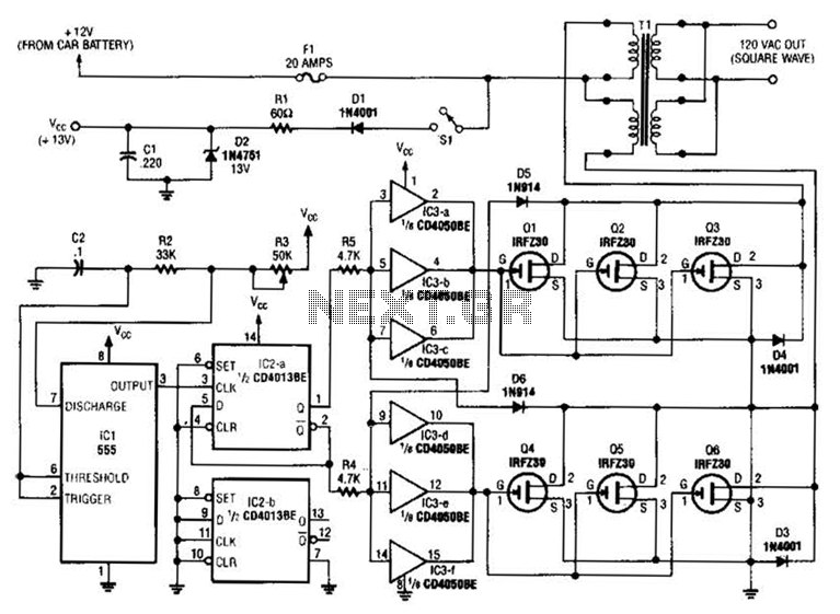
A 555 timer (IC1) generates a 120-Hz signal that is fed to a CD4013BE flip-flop (IC1-a), which divides the input frequency by two to generate a 60-Hz clocking frequency for the FET array (Q1 through Q6). Transformer T1 is...
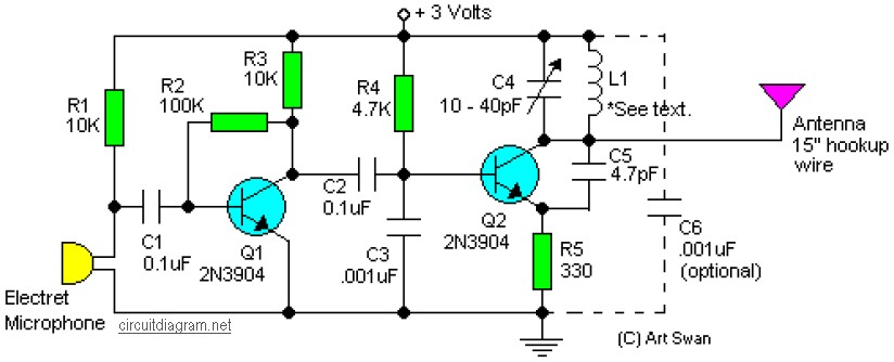
A simple and easy-to-build FM transmitter circuit that requires only two transistors. Typically, the default capacitor model is ceramic, preferably the NPO 1% type or an equivalent. However, almost any capacitor can be used in this circuit, but electrolytic...
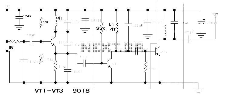
The components available were utilized to create a long-range FM radio transmitter operating within the 88-108 MHz band, designed for playing music. The circuit includes a power section that rectifies mains voltage to provide a stable 12V DC for...
This low-cost short-wave transmitter is tunable from 10 to 15 MHz using a ½J gang condenser (VC1), which determines the carrier frequency in conjunction with inductor L1. Frequency trimming is achieved with VC2. The carrier signal is amplified by...
This transmitter project is a highly efficient, rugged, and simple low-power continuous wave (C.W.) unit delivering more than 10W. It is crystal-controlled with stabilized high tension (H.T.) and features a buffer stage between the crystal oscillator and power amplifier...
P1 acts as the volume level for the condenser microphone. For the FM transmitter, the coil will be small. It is recommended to use thin gauge enamel magnet wire. The diameter of the coil should be a couple of...
Warning: include(partials/cookie-banner.php): Failed to open stream: Permission denied in /var/www/html/nextgr/view-circuit.php on line 713
Warning: include(): Failed opening 'partials/cookie-banner.php' for inclusion (include_path='.:/usr/share/php') in /var/www/html/nextgr/view-circuit.php on line 713