
simple short wave transmitter

This short-wave transmitter circuit is designed for effective communication within the frequency range of 10 to 15 MHz, making it suitable for various applications including amateur radio and educational projects. The tuning mechanism is facilitated by the ½J gang condenser (VC1), allowing the user to select the desired frequency by adjusting the capacitance in conjunction with inductor L1. The additional variable capacitor (VC2) provides fine-tuning capabilities to achieve precise frequency adjustments, ensuring minimal drift and stable operation.
Transistor T4 serves as the initial amplifier stage for the carrier signal, boosting its strength before it is fed into the RF amplifier stage, which is primarily constructed around transistor T1 (BD677). The transformer X1 plays a crucial role in coupling the amplified carrier signal to the RF amplifier, ensuring efficient signal transfer while isolating different stages of the circuit to prevent interference.
The audio input is captured by a condenser microphone (MIC), which converts sound waves into an electrical signal. This signal is then preamplified by transistor T3 (BC548), enhancing its amplitude to a suitable level for further processing. The amplified audio signal is subsequently fed into transistor T2 (BD139), which modulates the RF signal generated by T1. This modulation occurs by varying the current flowing through T1 in response to the audio signal, effectively imprinting the audio information onto the RF carrier wave.
RFC1 is strategically placed to block any RF signals from interfering with the power supply and the modulation stage, ensuring that the audio signal remains clear and undistorted. Finally, the modulated RF signal is coupled to the antenna through capacitor C9, allowing for effective transmission of the modulated signal into the airwaves.
Overall, this circuit design emphasizes simplicity and cost-effectiveness while providing essential functionalities for short-wave transmission. It combines various amplification stages and modulation techniques to achieve reliable performance in the designated frequency range.This low-cost short-wave transmitter is tunable from 10 to 15 MHz with the help of ½J gang condenser VC1, which determines the carrier frequency of the transmitter in conjunction with inductor L1. The frequency trimming can be done with VC2. The carrier is amplified by transistor T4 and coupled to RF amplifier transistor T1 (BD677) through transf
ormer X1*. The transmitter does not use any modulator transformer. The audio output from condenser MIC is preamplified by transistor T3 (BC548). The audio output from T3 is further amplified by transistor T2 (BD139), which modulates the RF amplifier built around transistor T1 by varying the current through it in accordance with the audio signal`s amplitude. RFC1 is used to block the carrier RF signal from transistor T2 and the power supply. The modulated RF is coupled to the antenna via capacitor C9. 🔗 External reference
Related Circuits
Telephones are declining globally; however, India has over 350 million mobile phone users, alongside a significant number of traditional telephone users. This telephone timer is designed to save costs by controlling unnecessary time spent during phone calls. This simple...
The three-transistor circuit costs less than $10 to build, uses commonly available components, and consumes less than 10 mA from a single 9V battery. By winding coil L1 as shown, the circuit can receive signals in the 5 to...
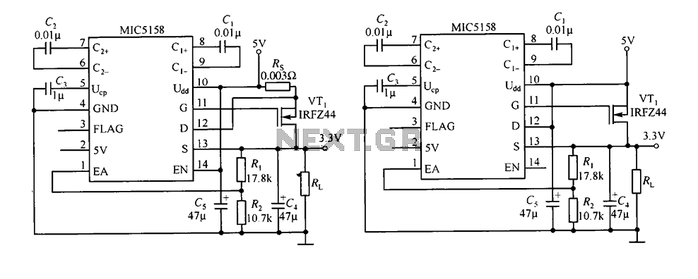
The circuit consists of peripheral components for the MIC5158, a linear regulator that converts a 5V input into a 3.3V output with a maximum current of 10A. When the input voltage (Ui) is 5V, an N-channel MOSFET, specifically the...
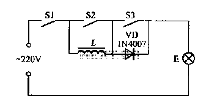
A portable four dimmer switch circuit is illustrated in Figure 8, featuring a four-speed brightness adjustment. When switches S1, S2, and S3 are all closed, the lamp operates at its brightest setting. When S1 and S2 are closed while...
This compact video transmitter is highly effective for short-distance video surveillance, operating efficiently up to 100 meters. It can be paired with either a black-and-white or infrared camera module, providing excellent image quality on standard color or black-and-white televisions....
A new project has been selected for the upcoming year, which is an improvement over the previous project, a homemade x-ray machine. The chosen project involves developing a safer and more efficient electronic device, replacing the homemade x-ray machine that...