
555 boost converter
Boost circuits serve as a practical solution for powering microcontrollers by increasing voltage from low-voltage battery sources. These circuits typically employ boost converters, which can be integrated into microcontrollers or implemented using discrete components. The Atmel ATtiny43U exemplifies the trend of integrating boost converters into microcontroller designs, allowing for simplified power management and enhanced functionality.
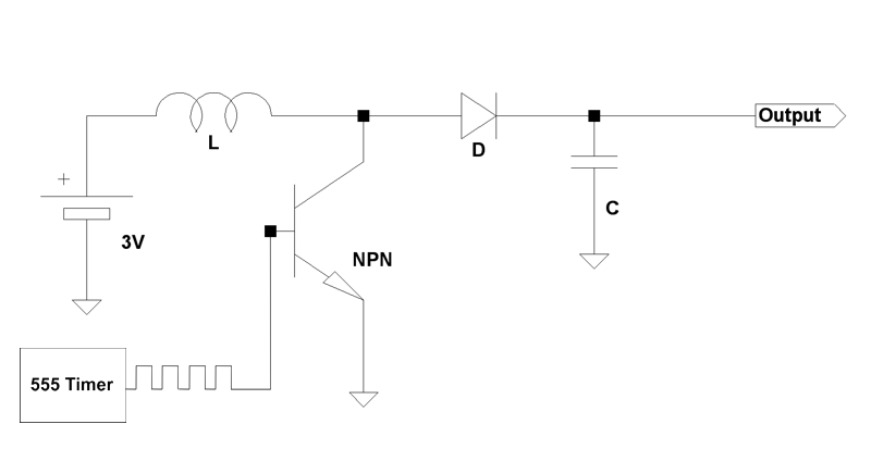
The 555 timer configuration presents a low-cost alternative for generating PWM signals to drive a boost converter. The 555 timer operates in astable mode, producing a square wave output that can be used to control the switching of a transistor, which in turn regulates the flow of current through an inductor. The inductor stores energy when the transistor is on and releases it to the load through a diode when the transistor is off, effectively increasing the voltage supplied to the load.
Key components of a basic boost converter circuit using a 555 timer include:
1. **555 Timer**: Configured to generate PWM signals. The frequency and duty cycle can be adjusted using external resistors and capacitors.
2. **Inductor**: Stores energy during the "on" phase of the PWM signal, which is crucial for boosting voltage.
3. **Diode**: Prevents backflow of current and allows the inductor's stored energy to charge the output capacitor.
4. **Output Capacitor**: Smooths the output voltage to provide a stable power supply to the load.
The performance of this circuit is contingent on the selection of components and the load characteristics. While the 555 timer provides a simple means of generating PWM, the inability to dynamically adjust the duty cycle in response to varying loads limits its application in scenarios where load conditions change frequently. For static loads, such as LED strings, the circuit can be optimized to achieve the desired output voltage.
In conclusion, while the 555 timer-based boost converter offers a low-cost solution for specific applications, its limitations in voltage regulation and dynamic response to load variations suggest that alternative PWM controllers may be more suitable for applications requiring robust performance and adaptability.Boost circuits are an awesome way to power microcontrollers. Instead of 4AA batteries or a 9V (usually regulated down to 5V or 3. 3V), you just boost one or two AA`s up to your desired voltage. The only problems are that boost ICs (like these two ) are a little expensive once you decide to make more than 2 or 3 of something, and the cheaper ones ar e hard to find in packages that can be hand soldered easily. I stumbled upon one great solution here use PWM from a microcontroller. And Atmel recently introduced the ATtiny43U with a built-in boost converter hopefully this will become a trend and all microcontrollers will come with built-in boost converters, the same way they (mostly) all support serial, I2C, and SPI. But in the meantime I wondered if a simpler solution might be possible, a boost converter using a 555 timer.
The 555 timer is a very common $0. 20 chip that can generate a PWM at a given frequency and duty cycle based on the charge time of some chosen resistors and a capacitor. The circuit would need the same basic external components as a boost converter (inductor, diode, capacitor), but it would be a lot cheaper.
It wouldn`t be able to regulate the voltage, only multiply it using a calculated duty cycle, so the solution already starts off a bit limited since the voltage of a AA battery varies over it`s lifetime. But despite this limitation, there are definitely applications where providing roughly 5V from a single AA or AAA is very useful (powering servos in a kite aerial photography rig, for example) Wikipedia has a great explanation of how a boost converter works.
The basic idea is that the source voltage is run through an inductor and alternately connected to ground through the transistor and disconnected so that it will charge the capacitor. The ratio of how long it`s connected to ground and how long it`s disconnected is the duty cycle, which determines the boosted voltage.
The math is pretty simple: D = 1 Vi/(Vo+0. 5) gives you the duty cycle you`ll need (the +0. 5 part is to compensate for the forward voltage of the diode). 555 timer calculators are available all over the Internet for choosing resistors and capacitor based on the duty cycle. As long as the frequency is in the KHz it should work. And when wired up it does work great until you attach a load, then the voltage drops precipitously. Higher frequencies seem to help a bit, but not enough. A higher duty cycle is needed to compensate for the load, which is how a boost converter handles the problem, but our simple 555 timer with its constant frequency and duty cycle is not up to the task.
If the load never varies powering a string of LEDs, for example - then you can play with the duty cycle to get the voltage you need under those conditions. Other than that, the only thing it`s useful for is charging a capacitor. If you wanted to boost a 1. 5V AAA battery up to 12V or 50V and release it all at once, this circuit can get it done. Use it to shock your cat. So a 555 timer isn`t very useful for a boost converter because there`s no easy way to adjust the duty cycle on-the-fly.
But inexpensive PWM controllers do exist perhaps I`ll try that next. 🔗 External reference
Related Circuits
At a T connection, the connections are clear, but at a cross, the connections are not clear, especially if there are no junction dots elsewhere in the schematic. It appears that the bottom of the I and the right...
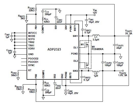
The ADP2323 DC-DC converter is designed to deliver two output voltages with specified maximum output currents. The first channel provides a 5-volt output with a maximum current of 2 Amperes, while the second channel supplies 1 volt with a...
This high voltage converter circuit operates from a 30-volt power supply and can output a voltage ranging from 0 to 3 kV in version 1 or from 0 to 10 kV in version 2. The high voltage converter circuit is...
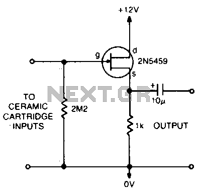
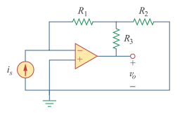
This circuit matches the very high impedance of ceramic cartridges, providing unity gain and low impedance output. By "loading" the cartridge with a 2.2MΩ input resistance, the cartridge characteristics are adjusted to closely compensate for the RIAA recording curve....
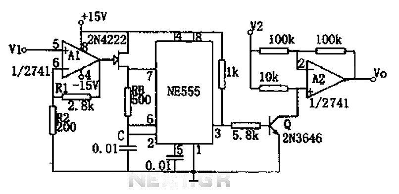
The circuit depicted in the figure consists of a voltage-frequency converter and an amplitude modulator. The input voltage V1, processed by operational amplifier A1, controls the FET 2N4222's internal resistance, which in turn alters the oscillation frequency of the...
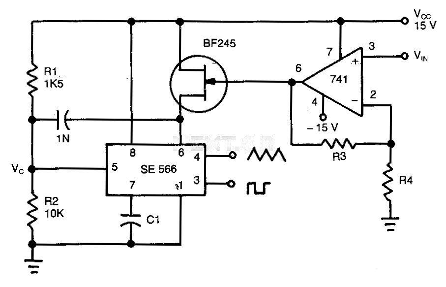
This circuit operates based on the frequency variation of the function generator in relation to the input voltage (ViN). The frequency is influenced by the capacitance and resistor connected to pin 6, with the resistor being substituted by a...
Warning: include(partials/cookie-banner.php): Failed to open stream: Permission denied in /var/www/html/nextgr/view-circuit.php on line 713
Warning: include(): Failed opening 'partials/cookie-banner.php' for inclusion (include_path='.:/usr/share/php') in /var/www/html/nextgr/view-circuit.php on line 713