
555 LED Flasher Circuit
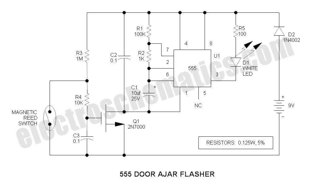
The 555 timer IC is configured in astable mode, allowing it to operate as a pulse generator. The circuit consists of several key components: the 555 timer IC, resistors, a potentiometer for adjusting the flash rate, and an LED. The two 1.5V batteries provide the necessary power supply, ensuring the circuit operates efficiently with minimal voltage drop.
In the basic configuration, the timing intervals are determined by the resistors and the capacitor connected to the 555 timer. The charging and discharging of the capacitor set the duration for which the LED remains on and off. By adjusting the potentiometer, the user can modify the resistance, thereby changing the timing intervals and achieving different flashing rates.
When the LED is connected as shown in Figure 2, the circuit operates with a longer ON time and shorter OFF time, which may be suitable for applications requiring a more prominent visual indication. However, this configuration leads to higher current draw, which can affect battery life.
In Figure 3, the introduction of a 22kΩ resistor in series with the 220kΩ potentiometer allows for a wider range of flash rates, providing versatility in the circuit's applications. This adjustment enables the user to fine-tune the timing characteristics according to specific needs, making it suitable for various projects where visual signaling is required.
Overall, this LED flasher circuit using the 555 timer IC is a simple yet effective solution for creating timed visual alerts in various applications, with the added benefit of adjustable timing through the use of resistors and a potentiometer.This is a small size led flasher built with the 555 timer IC that is powered from 2 x 1. 5V batteries. The circuit can be used as a flashing metronome, dark room timer, memo-reminder or other similar applications. In figure 1 the LED will be ON for a short period of time and OFF for a longer period. The duty cycle can be reversed if the LED is conn ected as shown in figure 2 but the battery consumption will also increase due to the fact that the LED will stay ON for a longer period of time. in figure 3 for a variable flash rate, replace the 220k pot with a 220k in series with a 22k resistor.
And that is a simple 555 led flasher circuit. 🔗 External reference
Related Circuits

IC1-c functions as a non-inverting comparator, while IC1-a operates as an inverting comparator. Potentiometer R1 and fixed resistors R2 and R3 create a voltage divider chain that provides slightly different voltages to the two comparators. These voltages establish the...
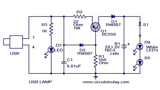
A simple USB LED lamp circuit utilizing a 5-volt power supply sourced from a USB port, designed to illuminate a desktop or laptop computer during power outages. The USB LED lamp circuit operates by converting the 5-volt DC power provided...
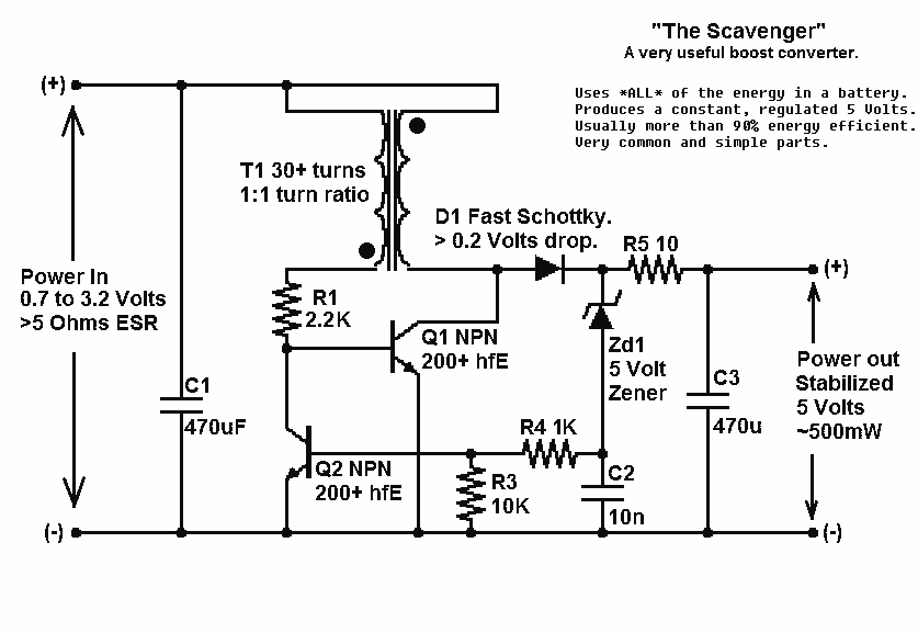
Presented here is a significant advancement in the design of simple, cost-effective, and efficient boost converters. To achieve an effective design, it is essential to convert current to voltage as efficiently as possible. This circuit excels in this regard. The...
This compact circuit is designed to be cost-effective, particularly useful during instances when the power supply is interrupted, such as while taking a shower. The backup lamp remains off as long as the CdS photocell is exposed to light...
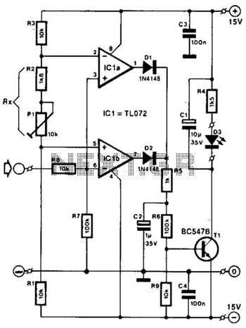
Two operational amplifiers are utilized as comparators to signal an excessive magnitude of an audio frequency (AF) signal, regardless of whether the signal is positive, negative, or asymmetrical. A reference voltage is established for both operational amplifiers using a...
The TCM3105 FSK modem chip from Texas Instruments enables the construction of a modem compatible with Bell 202 or CCITT V23 standards. This modem circuit can transmit data at baud rates of 75, 150, 600, and 1200, and receive...
Warning: include(partials/cookie-banner.php): Failed to open stream: Permission denied in /var/www/html/nextgr/view-circuit.php on line 713
Warning: include(): Failed opening 'partials/cookie-banner.php' for inclusion (include_path='.:/usr/share/php') in /var/www/html/nextgr/view-circuit.php on line 713