
USB LED Lamp Circuit using 5 Volts

The USB LED lamp circuit operates by converting the 5-volt DC power provided by a USB port into sufficient power to drive one or more light-emitting diodes (LEDs). The circuit typically includes a USB connector, a current-limiting resistor, and the LEDs themselves.
The USB connector serves as the interface to connect the lamp to any standard USB power source, such as a computer or a USB wall adapter. The current-limiting resistor is crucial as it prevents excessive current from flowing through the LEDs, which could otherwise lead to damage. The value of this resistor is calculated based on the forward voltage and current specifications of the LEDs used in the circuit.
For instance, if the forward voltage of the LED is approximately 2 volts, and the desired forward current is 20 mA, the resistor can be calculated using Ohm's law. The voltage drop across the resistor will be the difference between the USB supply voltage and the LED forward voltage, which is 3 volts in this case. The resistor value can be calculated as follows:
R = V/I = 3V / 0.02A = 150 ohms.
In practical applications, a standard resistor value of 150 ohms or 180 ohms can be used. The circuit can be configured to connect multiple LEDs in series or parallel, depending on the desired brightness and the total forward voltage of the LED configuration.
The assembly of the circuit can be done on a small PCB or a breadboard for prototyping. The LEDs can be mounted directly to the board, and the connections should be soldered securely to ensure reliability. The final assembly can include a protective casing to prevent damage from external factors and to enhance portability.
This USB LED lamp circuit is particularly useful for providing illumination in low-light conditions, making it an effective solution for temporary lighting needs during power failures. The simplicity of the design allows for easy replication and modification, which can be tailored to specific lighting requirements or aesthetic preferences.A simple usb LED lamp circuit using 5 volts power supply from usb port, which can be used to light a desktop or laptop computer during power failure.. 🔗 External reference
Related Circuits

This is a component of a 100W RF amplifier. This circuit is constructed using the RF power transistor BLY94. Components include the BLY94 transistor, inductor, and others. The 100W RF amplifier circuit utilizing the BLY94 transistor is designed to amplify...

This is an interesting hobby circuit for a crank doorbell. The circuit is built around a 555 timer and a musical piezo buzzer, powered by a 9-volt battery. A single 9-volt PP3/6F22 compact battery is sufficient to power the...
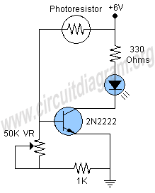
This project involves a simple and engaging light-activated LED circuit that illuminates an LED in response to light exposure. The circuit is straightforward to construct, requiring only six components. A photoresistor is utilized for light sensing, while a 2N2222...

In certain industries, a computer-controlled 4-20 mA current loop is utilized to manage various equipment. This current loop is employed to transmit a signal over a distance. The 4-20 mA current loop is a standard method for transmitting analog signals...

The continuity tester consists of a battery and a lamp connected in series, with one end of the circuit terminated with an alligator clip and the other end connected to the probe tip. The continuity tester is a fundamental...

The Tupperware Turret circuit is designed to be straightforward while ensuring full functionality. The primary components in the schematic include the PIC 18F4520 microcontroller, servo motors, an infrared (IR) receiver, and a TIP120 transistor. This project is powered by...