
555 lights remind

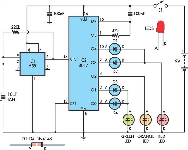
The circuit operates on the principle of a monostable multivibrator, utilizing a 555 timer IC, which is a versatile component in electronic circuits. In this configuration, the 555 timer is set up to generate a single output pulse when triggered. The timing interval is determined by the values of R1 (the resistor) and C3 (the capacitor), which form the RC time constant.
When power is applied, the circuit remains in a stable state until it is triggered by a momentary action, such as closing a switch. The trigger input of the 555 timer is connected to the relay, which is activated when the lights are turned on. This action causes the capacitor C3 to begin charging through R1. The charging process is exponential, and the voltage across C3 increases until it reaches the threshold level of approximately 2/3 VDD.
Upon reaching this threshold, the 555 timer switches its output state from high to low. This transition activates the output pin connected to the buzzer and the LED circuit. The buzzer emits a sound, and the LEDs light up, providing a visual and auditory reminder to the driver. The duration of this alert signal corresponds to the time it takes for C3 to discharge through R1 once the trigger is removed, effectively providing a reminder for a predetermined time.
To adjust the delay time, one can modify the resistance value of R1 or the capacitance value of C3. Increasing either component will lengthen the delay, while decreasing them will shorten it. This flexibility allows for customization based on specific requirements or preferences.
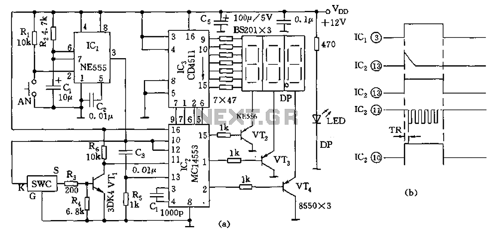
In summary, this circuit is a practical solution for alerting drivers to turn off their lights, utilizing a simple yet effective monostable delay configuration that combines visual and auditory signals to enhance safety and prevent battery drain. As shown for the lights to remind the circuit. The circuit consists of monostable delay circuit, driving circuit, buzzer, light-emitting diodes and other components. Wherein th e one-shot output signal from the delay circuit 555 and R1, C3 composed of control behind the circuit.After the lights from the direction of the lamp power supply circuit in the relay through the diode is added to 555 feet, so that the capacitor C3 is charged via R1. As the charging progresses, foot potential rise when foot potential reaches 2/3VDD (approximately l minute delay) after 555 rollover occurs, low output enable pin BG conduction.
Corresponding drive LED light, buzzer, the sound and light signals to alert drivers timely lights.Circuit in the lights corresponding to the length of time that is the delay time of the circuit can be changed by adjusting the time constant R1C3. When this circuit is implemented in the direction of the driver forgot to turn off lights, turn off the power in time to remind drivers.
Related Circuits
Children today often possess a wide array of toys available in stores. For those with a son or grandson who has a collection of toy cars, a handmade gift such as a set of traffic lights would be greatly...
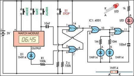
This device serves as a daily medication reminder. It incorporates a crystal watch and a 4001 quad 2-input NOR gate, with two of the gates (IC1a & IC1b) configured as an RS flip-flop. The watch is programmed to alert...
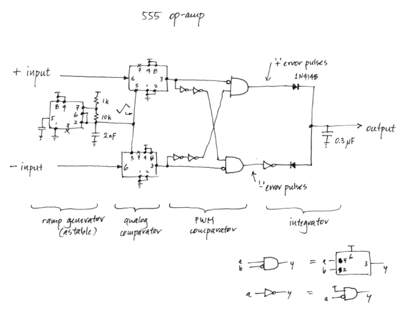
Is it feasible to create an operational amplifier using only 555 timer chips and passive components? While this may not be a practical inquiry, given the availability of low-cost and efficient op-amps, it does have some aesthetic interest. In...
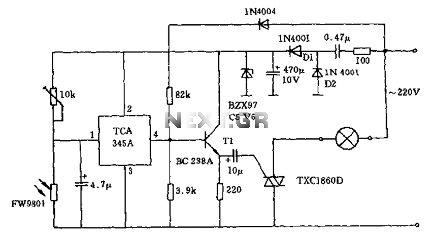
A 200W lamp switch control operates at a power supply voltage of 220V. It automatically turns the light on or off based on ambient illumination levels, specifically activating at approximately 100 lux. In low light conditions, a time-sensitive resistor...
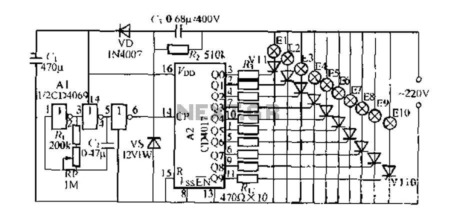
The digital integrated circuit consists of a controller for a string of ten road flashing lights, which drives the El-El0 string lights in a flashing cycle. The system utilizes a ten-count decoder, specifically the CD4017 digital integrated circuit. When...
The digital thermometer consists of a temperature sensor, a single stabilizing circuit, a counter circuit, a decoding section, a driving circuit, and LED digital tubes among other components. It operates within a temperature range of 0 to 50 degrees...