
Traffic Lights For Model Cars Or Model Railways

The traffic light circuit is a practical and engaging project that combines basic electronics with creativity. The central component, the 555 timer IC, is well-known for its versatility in generating precise timing sequences. In this application, it provides a stable clock signal that dictates the operation of the traffic lights. The choice of a 220 kΩ resistor and a 10 µF capacitor is critical, as these values are selected to achieve a timing period that is visually effective for the intended use with toy cars.
The 4017 decade counter is another vital component, serving the purpose of sequentially activating the LEDs. Each output of the 4017 corresponds to a specific light state: green, orange, and red. The use of 1N4148 diodes to combine outputs for the red and green LEDs enables a more extended illumination time, enhancing the realism of the traffic light operation. The design ensures that the transitions between lights are smooth and logical, mimicking real-world traffic signals.
Powering the circuit with a 9V battery is a practical choice, as it provides sufficient voltage for the operation of the LEDs while remaining within the safe operational limits of the 4017. The absence of current-limiting resistors is a design decision that takes advantage of the current-limiting characteristics of the 4017, allowing for a simple and efficient circuit layout.
For those interested in expanding the project, adding a second set of traffic lights for cross traffic introduces additional complexity and educational value. By synchronizing the two sets of lights, users can simulate more realistic traffic scenarios. This aspect of the project encourages experimentation and learning about timing, synchronization, and the operation of electronic components in a fun and engaging way. Overall, this traffic light circuit serves as an excellent introduction to basic electronics for hobbyists and young engineers alike.Kids these days seem to have most things you see in the toy shops, so if you have a son or grandson who has a collection of cars, here is something he will really appreciate. And it will be really special as you will be giving something made by you - a set of traffic lights for his cars.
This traffic light circuit uses a 555 timer IC as the master timer. The 220kO timing resistor and 10 µF capacitor control the timing pulses, giving a period of about three seconds. The 3-second output pulses are used to clock a 4017 decade counter whose outputs directly drive the green, orange and red LEDs.
To obtain a longer time for the red and green lights compared with the orange light, two outputs are ORed using 1N4148 diodes for the red and green LEDs, while the orange is driven by one output only. This gives about 6 seconds for the red and green LEDs and 3 seconds for the orange. When power is first applied, the RC network connected to pins 1 and 15 of IC2 resets the 4017 and the green LED cycle begins.
The orange and red cycles follow and at the end of the red cycle, pin 1 will go high to reset the 4017 to start the green cycle all over again. You can experiment with the cycle times by adjusting the 220kO resistor or by combining more or less 4017 outputs to achieve different ON times for the three LEDs.
The circuit is designed to be powered by a 9V battery and this is the maximum voltage that is recommended. This is because the LEDs are directly driven by the 4017 with no current limiting resistor being used.
The 4017 naturally limits the current that it can supply to 15mA. An extension of this project would be to make a second set of lights for the cross traffic. Here you would use the same 555 as a master timer for both sets of lights (otherwise chaos would ensue) and a separate 4017 to drive the three extra LEDs. Of course, you would have to take care and ensure that green and orange outputs on each set of lights correspond with red on the other!
🔗 External reference
Related Circuits
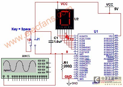
Multisim is circuit simulation software based on SPICE, which stands for Simulation Program with Integrated Circuit Emphasis. Developed in 1975 at the University of California, Berkeley, it focuses on simulating integrated circuits. In Multisim 9, the MultiMCU module must...
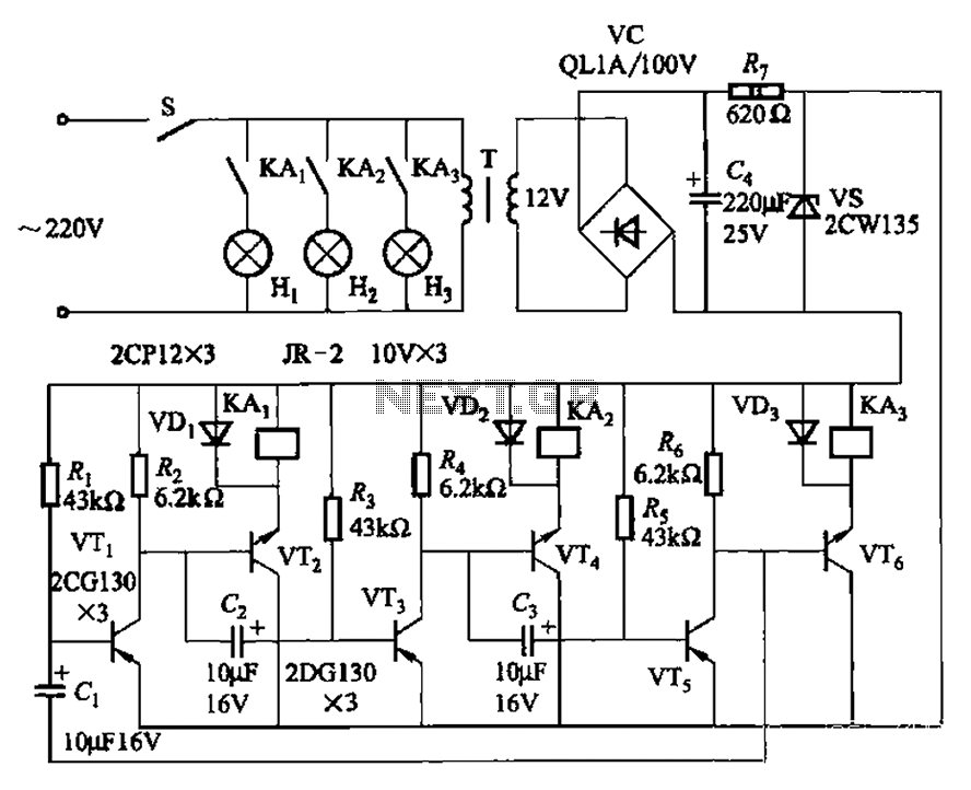
The transistors VTi, VT3, and VTs, along with the RC components, form three distinct multi-resonator oscillators. The oscillation frequency levels are dependent on the values of Ri, R3, Rs, and Cl, as well as Cz and C3s. The circuit comprises...
To troubleshoot the headlight system, switch the headlight switch ON and OFF and check if the headlight relay can be felt and heard clicking. This is indicated in the first schematic on the left side of the diagram. The...
An intriguing lighting solution for bicycles, utilizing LEDs. It features low power consumption and includes a circuit diagram for an electronics project, operating at 9V, utilizing the NE555 timer. The bicycle lighting circuit employs a NE555 timer IC configured in...
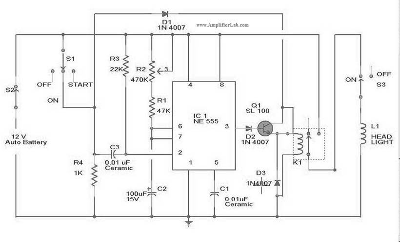
The circuit diagram for the automatic headlights turn-off circuit is presented here. This circuit can be installed in a car. The automatic headlights turn-off circuit is designed to enhance vehicle safety and convenience by ensuring that the headlights are automatically...
A 1999 Chevrolet Suburban has non-functional headlights. The fuses and circuit breakers have been checked and found to be operational. According to the owner's manual, the headlamps are protected by a circuit breaker located within the lamp switch, but...