
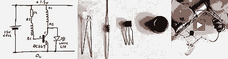
555 meter circuit diagram of a DC voltage
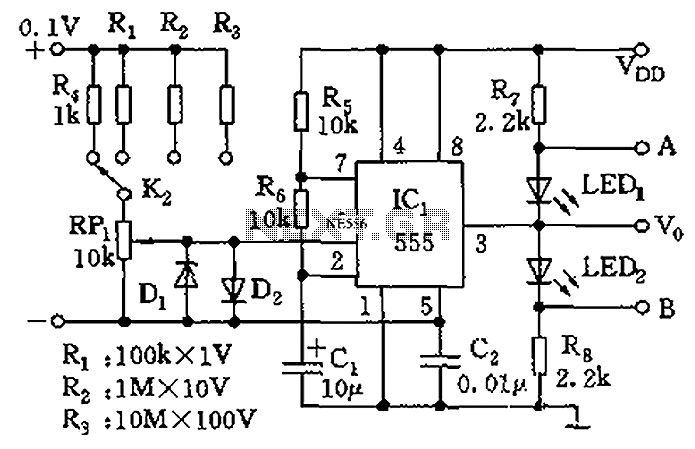
The described circuit utilizes a 555 timer integrated circuit configured in a comparator mode to detect and compare input voltage levels. The control terminal (5 feet) is connected to a reference voltage, while the threshold terminal (6 feet) receives the input voltage to be measured. The internal comparators of the 555 timer will trigger an output when the voltage at the threshold terminal exceeds the reference voltage by a small margin, specifically 5 mV.
When a DC voltage is applied across the designated terminals, the circuit is designed to illuminate LED1 when the input voltage is above the reference level and LED2 when it is below. This visual indication provides immediate feedback on the voltage level being measured.
The resistance value of RP1 can be adjusted to modify the sensitivity of the measurement. As the resistance changes, the range of voltage that can be effectively measured is altered, allowing for a versatile application across different voltage levels. The alternation of the two LEDs serves as an indicator of the current measurement range, with the specific range being determined by the setting of RP1.
The voltage measurement ranges are clearly defined as follows: 0-1V for low voltage applications, 0-10V for moderate voltage scenarios, 0-100V for higher voltage measurements, and 0-1000V for very high voltage applications. This multi-range capability makes the circuit suitable for various electronic testing and monitoring tasks, ensuring that it can accommodate a wide spectrum of voltage levels while providing reliable and accurate readings. As shown, the control terminal 5 feet and 555 threshold end 6 feet is actually two internal input voltage comparator I, as long as 6 feet voltage is higher than 5 feet 5mV, the n 555 will reliably trigger. Applying a DC voltage to the figure of + - terminal, if the voltage is high, LED1 light; low voltage, LED2 light. Change the range and RP1, when the two alternately flashing arc tube, the range is multiplied by RP1 indicators, is the measured voltage V number.
Fourth gear measuring range: 0-1V, 0-10V, 0-100V, 0-1000V.
Related Circuits
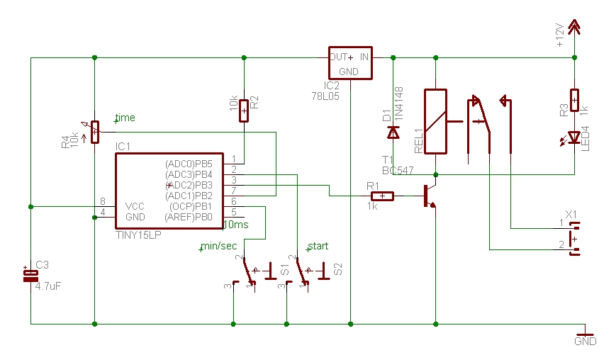
The time can be set using a potentiometer ranging from 1 minute to 1023 minutes, approximately 17 hours. A pushbutton initiates the timing process, activates a relay, and the timer will deactivate the relay once the set time has...
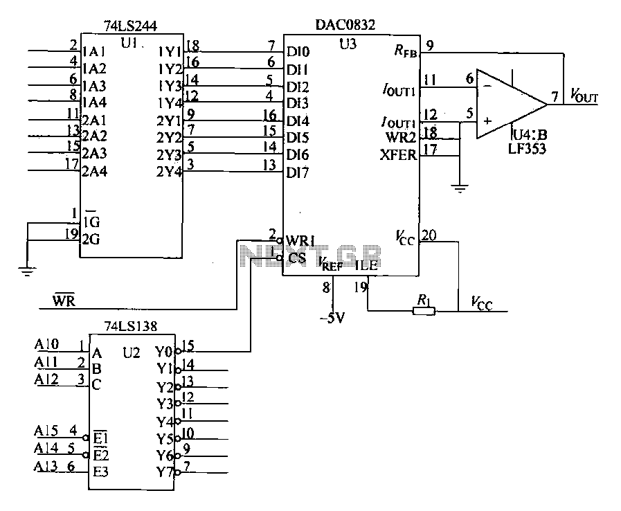
The DAC0832 is depicted in Figure 27-13 as a single-phase circuit connected to the 8086 CPU. The internal 8-bit data input of the DAC0832 must be interfaced with the CPU and the D/A converter interface circuits for data transmission,...
The DTMF infrared remote control circuit utilizes a DTMF encoded signal that can be decoded by a specialized decoder and the PLL audio decoder LM567. However, a DTMF encoded signal decoded by a single decoder yields only one frequency....
This circuit can be utilized in various devices to extract residual energy from seemingly depleted batteries. It is possible to connect multiple dead batteries in order to maximize energy extraction. This circuit design, often referred to as a Joule Thief,...
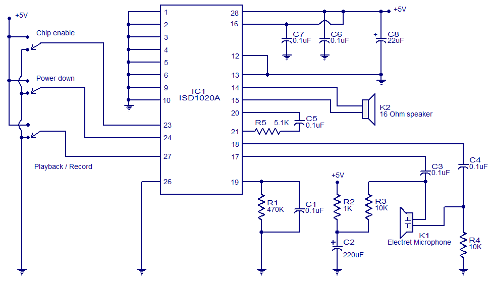
This circuit is designed in response to a request made by Mr. Vignesh for a voice recording and playback system. The circuit utilizes the ISD1020A IC from ISD, which is a CMOS single-chip record/playback device capable of recording voice...
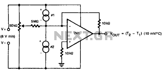
The 50 k ohm potentiometer adjusts offsets in devices, whether internal or external, allowing for the setting of the difference interval size. This feature makes it suitable for liquid-level detection, particularly in scenarios where a measurable temperature difference exists. The...