
DAC0832 interface circuit with the 8-bit CPU
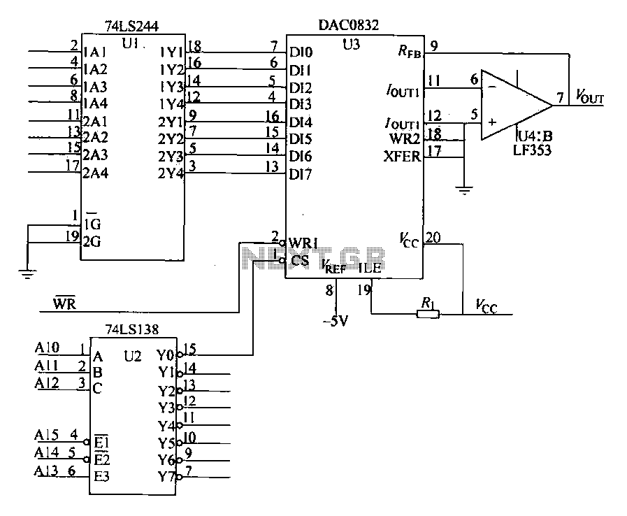
The DAC0832 is a dual 8-bit digital-to-analog converter (DAC) that interfaces seamlessly with microprocessors like the 8086. It is designed to convert digital binary data into an analog voltage output, which can be utilized in various applications such as audio processing, signal generation, and control systems. The connection between the 8086 CPU and the DAC0832 is facilitated through a systematic arrangement of data and control lines, ensuring effective communication and data transfer.
In the circuit, the data lines from the CPU (DO to D7) are routed through a line driver (74LS244), which strengthens the signal integrity and drive capability of the data bus. This step is crucial, especially when multiple devices are connected to the same bus, as it minimizes the risk of signal degradation and ensures reliable data transmission.
The write control line (WR) is pivotal for the operation of the DAC0832, as it signals the DAC to latch the incoming data from the CPU. The address decoding is managed by a 3-to-8 decoder (74LS138), which interprets the address signals from the CPU’s address lines (A10 to A15) to activate the corresponding DAC input. The address range of 2000H to 23FFH allows for multiple devices to be connected and controlled within the same memory space, enhancing the flexibility of the system design.
When the CPU executes an output instruction, the 8-bit binary data is sent to the DAC0832, which then converts this digital signal into an analog output voltage (VOUT). This output is typically buffered through an operational amplifier to ensure that the analog signal is stable and capable of driving external loads effectively. The operational amplifier can also be configured to adjust the output voltage range or to provide additional gain, depending on the application requirements.
In summary, the integration of the DAC0832 with the 8086 CPU through a well-structured interface circuit exemplifies a robust method for digital-to-analog conversion, facilitating various electronic applications that require precise analog signal generation from digital data.DAC0832 shown in Figure 27-13 cushion in the form of a single-phase circuit connected with 8086CPU. Since DAC0832 internal 8-bit data input must be set between the CPU and D/A converter interface circuits for data transmission, read and write address selection and control, if D/A core chip internal registers no input, you will also need additional register, starting from the reliability of the system, additional data on the interface buffer is necessary. Figure 27-14 DAC0832 interface circuit and the CPU. DO ~ D7 from the CPU over the eight data lines, in order to improve the data bus drive capability, DO ~ D7 to go through the data line drive Ul (74LS244) t then received DAC0832 data input terminal (D10-D17), as WR write control line of the CPU; AlO ~ A15 address line of CPU, the U2 (74LS138) to generate the interface after 3-8 decoder decodes the address signal, since the address lines AO-A9 did not participate in the decoding, 27-14 in FIG.
DAC0832 interface address is 2000H ~ 23FFH. When you need to enter when the line of D/A conversion, CPU only execute an output instruction, it can be 8-bit data is converted by DO ~ D7 UI passed through the data input terminal DAC0832 Dl0-DI7; and start D/A converter immediately in the op amp output corresponding analog output voltage VOUT.
Related Circuits
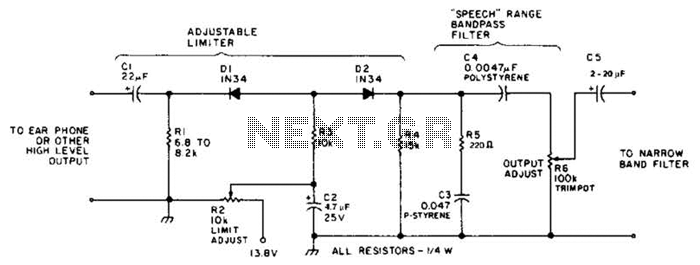
This circuit employs a diode series clipper to limit noise peaks on a received signal. It is most effective in scenarios where several volts peak-to-peak of audio signal are present. The diode series clipper circuit is designed to protect subsequent...
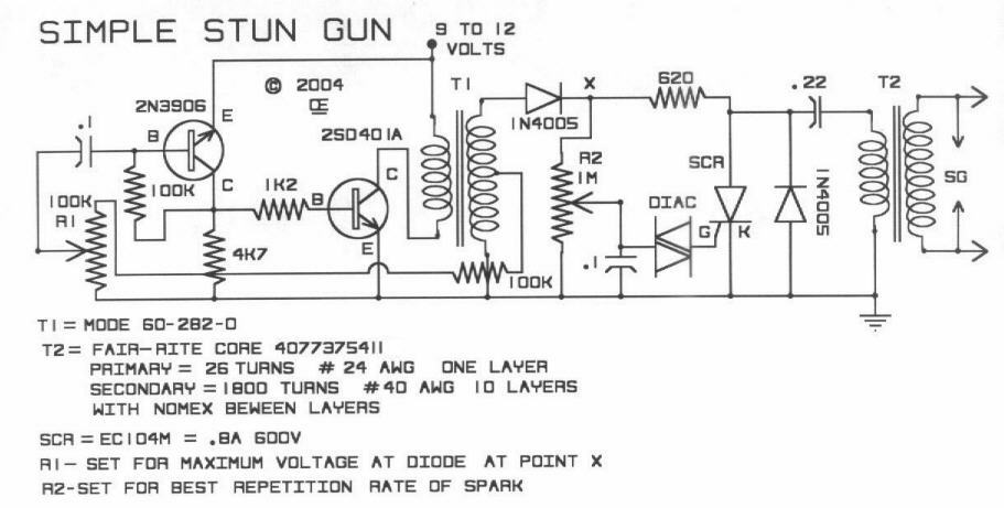
This is a DIY simple stun gun circuit presented solely for educational purposes. There is no recommendation for constructing these stun guns or for their actual use in any capacity. The circuit for a DIY stun gun typically consists of...
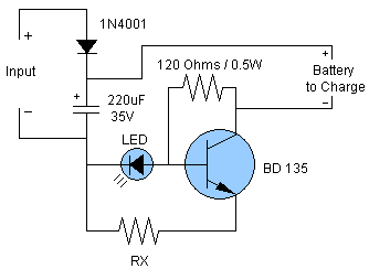
Schematic and description of a simple and easy-to-build NiCd and NiMH battery charger circuit that is capable of charging multiple NiCd and NiMH batteries. The circuit for the NiCd and NiMH battery charger is designed to be straightforward, allowing for...

The interface circuit is placed between the computer's standard video signal output terminal and the television. It amplifies the standard 1V (Peak-to-Peak) video signal to 3V (Peak-to-Peak). The negative feedback circuit consists of transistors T1 and T2, providing a...
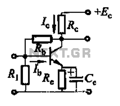
Basic reference transistor bias circuit - Mixed Negative feedback The basic reference transistor bias circuit utilizing mixed negative feedback is a fundamental electronic configuration designed to stabilize the operating point of a transistor. This circuit typically employs a combination of...
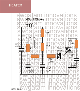
Controlling heaters rated up to 1500 watts requires stringent specifications for the controlling unit to ensure safe and effective operation. The introduction of advanced snubber-less Triacs and Diacs has made it relatively easier to implement heater controllers at high...