
555 ramp generator

This circuit demonstrates two distinct methods of charging a capacitor using a 555 timer IC. The first method employs a traditional RC charging approach, where the capacitor charges through a resistor, displaying a characteristic exponential voltage curve. The second method utilizes a constant-current source provided by a current mirror circuit, allowing for a linear voltage increase across the capacitor. The comparison between these two methods highlights the differences in charging behavior, providing insight into the effects of varying current sources on capacitor charging. The use of a digital voltmeter and ammeter facilitates precise measurements, enabling a thorough analysis of the circuit's performance under different conditions. The experimentation with temperature effects on the current mirror transistors further illustrates the importance of thermal management in precision electronic circuits. Overall, this circuit serves as an educational platform for understanding capacitor charging dynamics and the impact of circuit configurations on performance.The voltage rating on the 470 µF capacitor is not critical, so long as it generously exceeds the maximum power supply voltage. In this particular circuit, that maximum voltage is 12 volts. Be sure you connect this capacitor in the circuit properly, respecting polarity! Again, we are using a 555 timer IC as an astable multivibrator, or oscillator. This time, however, we will compare its operation in two different capacitor-charging modes: traditional RC and constant-current. Connecting test point #1 (TP1) to test point #3 (TP3) using a jumper wire. This allows the capacitor to charge through a 47 k © resistor. When the capacitor has reached 2/3 supply voltage, the 555 timer switches to "discharge" mode and discharges the capacitor to a level of 1/3 supply voltage almost immediately.
The charging cycle begins again at this point. Measure voltage directly across the capacitor with a voltmeter (a digital voltmeter is preferred), and note the rate of capacitor charging over time. It should rise quickly at first, then taper off as it builds up to 2/3 supply voltage, just as you would expect from an RC charging circuit.
Remove the jumper wire from TP3, and re-connect it to TP2. This allows the capacitor to be charged through the controlled-current leg of a current mirror circuit formed by the two PNP transistors. Measure voltage directly across the capacitor again, noting the difference in charging rate over time as compared to the last circuit configuration.
By connecting TP1 to TP2, the capacitor receives a nearly constant charging current. Constant capacitor charging current yields a voltage curve that is linear, as described by the equation i = C(de/dt). If the capacitor`s current is constant, so will be its rate-of-change of voltage over time. The result is a "ramp" waveform rather than a "sawtooth" waveform: The capacitor`s charging current may be directly measured by substituting an ammeter in place of the jumper wire.
The ammeter will need to be set to measure a current in the range of hundreds of microamps (tenths of a milliamp). Connected between TP1 and TP3, you should see a current that starts at a relatively high value at the beginning of the charging cycle, and tapers off toward the end.
Connected between TP1 and TP2, however, the current will be much more stable. It is an interesting experiment at this point to change the temperature of either current mirror transistor by touching it with your finger. As the transistor warms, it will conduct more collector current for the same base-emitter voltage. If the controlling transistor (the one connected to the 100 k © resistor) is touched, the current decreases.
If the controlled transistor is touched, the current increases. For the most stable current mirror operation, the two transistors should be cemented together so that their temperatures never differ by any substantial amount. This circuit works just as well at high frequencies as it does at low frequencies. Replace the 470 µF capacitor with a 0. 1 µF capacitor, and use an audio detector to sense the voltage waveform at the 555`s output terminal.
The detector should produce an audio tone that is easy to hear. The capacitor`s voltage will now be changing much too fast to view with a voltmeter in the DC mode, but we can still measure capacitor current with an ammeter. With the ammeter connected between TP1 and TP3 (RC mode), measure both DC microamps and AC microamps.
Record these current figures on paper. Now, connect the ammeter between TP1 and TP2 (constant-current mode). Measure both DC microamps and AC microamps, noting any differences in current readings between this circuit configuration and the last one. Measuring AC current in addition to DC current is an easy way to determine which circuit configuration gives the most stable charging current.
If the current mirror circuit were perfect - the capacitor charging current absolutely constant - there wou 🔗 External reference
Related Circuits
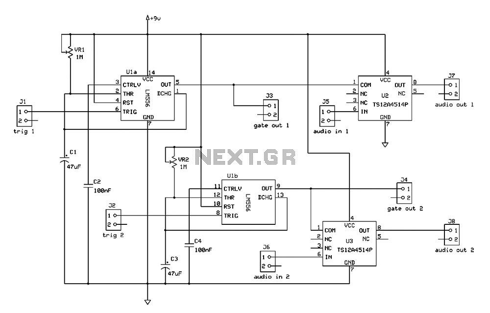
The Switchgate is a simple dual gate circuit based on a 556 timer configured in monostable mode, featuring a trigger input that activates two switches. The outputs of the monostables are also available individually. Recent research has led to...
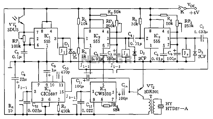
The circuit consists of four light-controlled electronic switches, timing circuits, voice circuits, audio circuits, and other components. It is designed to celebrate birthdays or similar occasions, with features such as birthday candles that can be lit or extinguished. The...
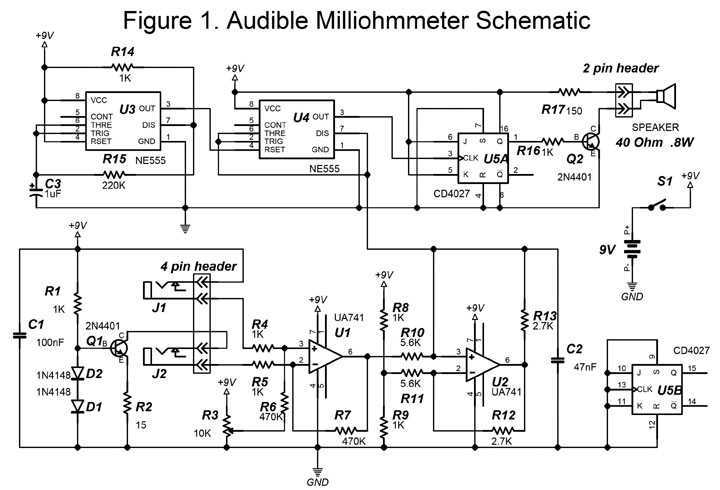
This project uses a four-point resistance measurement process also known as the Kelvin method. This procedure uses a current source to determine the value of an unidentified resistance. A constant current flows through the unknown resistance and the voltage...
The HV739 is a monolithic single-channel, high-speed, high-voltage ultrasound transmitter pulser. This integrated, high-performance circuit is housed in a single 5x5 mm, 32-lead QFN package. The HV739 can deliver up to ±3.0 A of source and sink current to...
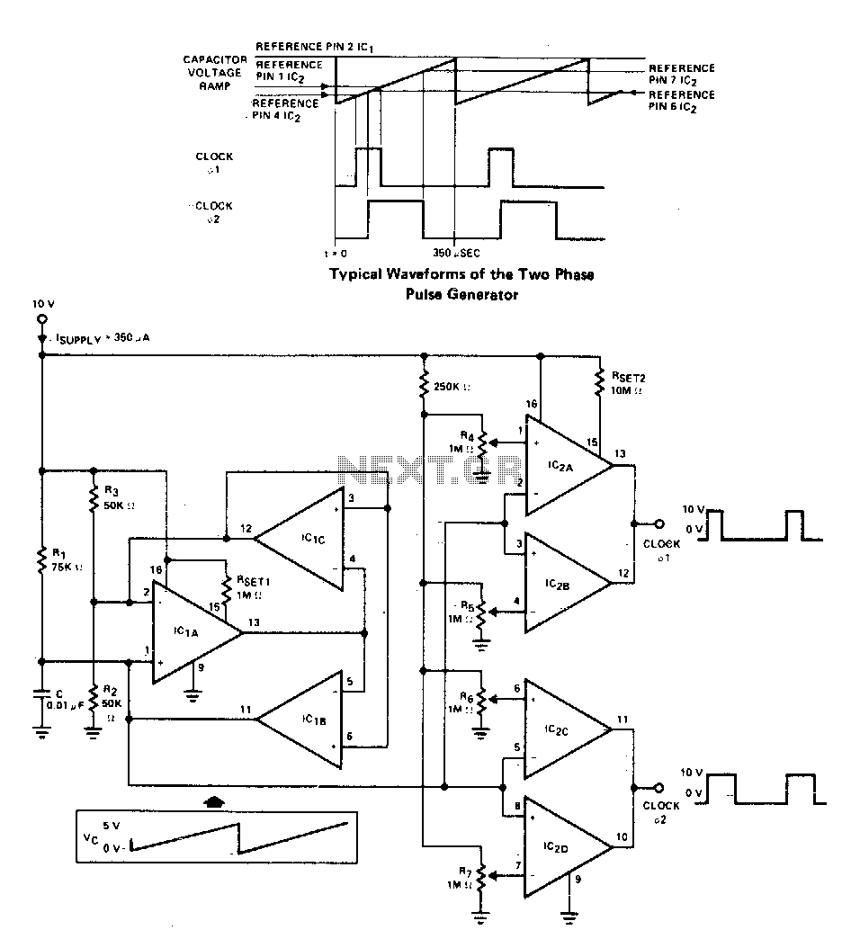
A two-phase clock generator utilizes two L161 integrated circuits to produce pulses with adjustable widths and phase relationships. Additionally, a ramp generator supplies input to two variable window comparators, which are configured using IC2A-IC2B and IC2C-IC2D, respectively. The two-phase clock...
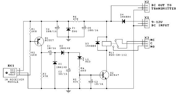
This door minder electronic project is based on a 555 timer circuit and utilizes an infrared (IR) beam to monitor doorways, passageways, or any other designated area. When the IR beam is interrupted, a relay is activated, which can...