
555 tachometer circuit diagram
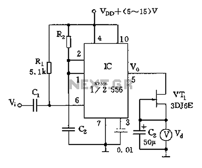
The described circuit operates by converting mechanical rotational speed into an electrical signal that can be easily interpreted. The signal Vi, representing the speed pulse, is first processed through a differential amplifier stage, which enhances the signal quality before it reaches the trigger input of the 555 timer. The timer is set up in a monostable configuration, meaning it will output a single pulse in response to each trigger event.
The pulse width generated by the timer is determined by the resistors and capacitor in the circuit, specifically through the formula td = 1.1R2C2, where R2 is the resistance connected to the discharge pin of the timer and C2 is the timing capacitor. This pulse width remains constant regardless of the input frequency, allowing for accurate timing control.
As the rotational speed increases, the frequency of the input speed pulse Vi also increases, resulting in a greater number of output pulses from the timer. These output pulses are then transformed into a voltage signal using a constant current source (VT1), which ensures that the integration process through capacitor C3 produces a smooth and proportional voltage output. This output voltage is directly related to the rotational speed of the mechanical system being measured.
The final voltage output can be connected to a digital readout meter, providing a clear and precise display of the speed. This circuit is particularly useful in applications where speed monitoring is critical, such as in automotive systems, industrial machinery, or any rotating equipment where accurate speed measurement is essential. The design emphasizes stability and reliability, making it a valuable tool in electronic speed measurement systems. As shown from the switch contacts, proportional to the speed pulse signal Vi, after the differential is added to IC (1/2 556) trigger side to make the single stabilizing circui t generates a pulse of fixed width, td 1.1R2C2, different speed has its proportional number of pulses, one-shot pulse output by the constant current source VT1 and C3 integral to obtain a voltage proportional to the rotational speed, it can speed digital readout on the meter. This circuit is also referred to as the rate of voltage conversion circuit.
Related Circuits
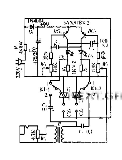
A 220V mains power supply is reduced using a control circuit designed by N. Guanidine D. Yi. The circuit features a spike Bode and provides a +9V voltage supply. It includes components such as a control port (G), a...
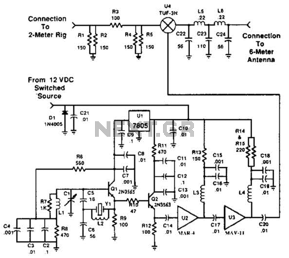
This transverter utilizes the bilateral properties of a balanced mixer to generate a 6-meter output from 2-meter inputs. The component Y1 is a 90-MHz crystal. It is important to note that the input frequency on the 2-meter band is...
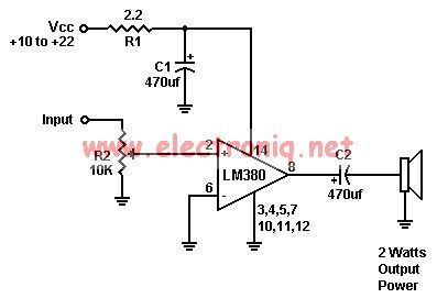
A simple audio amplifier can be designed using the LM380 along with a few external components. This amplifier features a wide supply voltage range, an input impedance of 150 kΩ, low distortion, and a current capability of 1.3 A. The...
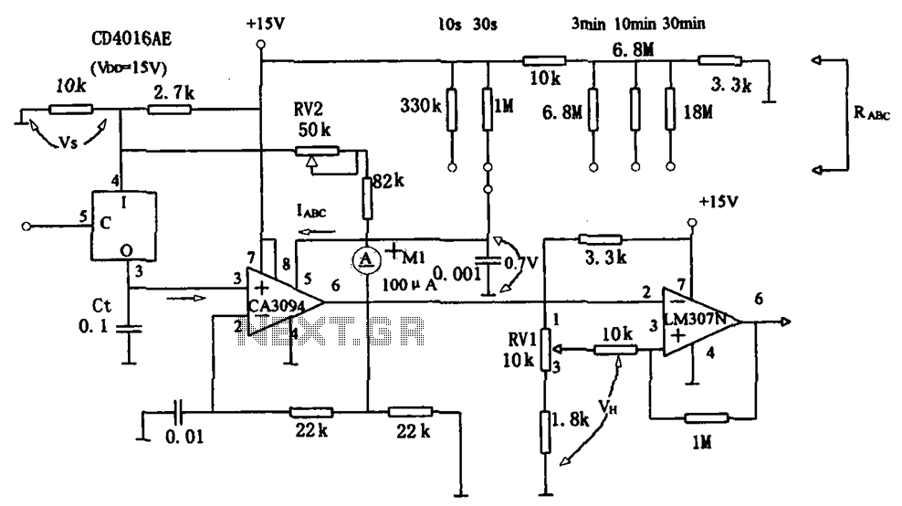
The long timer circuit utilizes an operational amplifier, specifically the CA3094, to control the discharge formula for extended timing. This is typically achieved by adjusting the variable resistor RV1, which alters the timing duration to meet specific requirements. The long...
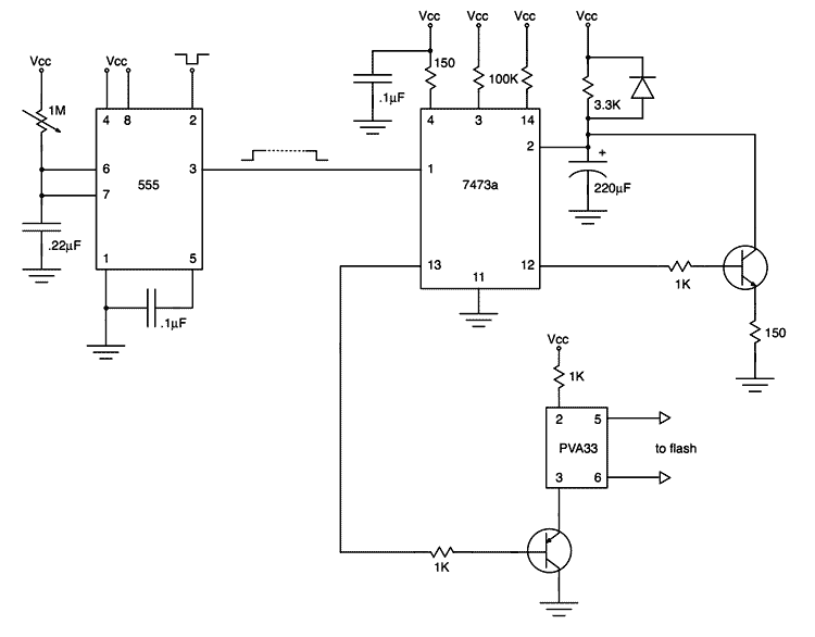
My first project after assembling an electronic design lab was to build a flash trigger that I could use for high-speed photography. I thought it would be useful to share not only the finished product but also the reasoning...
L1 is 0.112uH (this tunes to the middle of the FM band, 98 MHz, with VC1 at its centre value of 33pF). L1 is 5 turns of 22 swg enamelled copper wire close-wound on a 5mm (3/16") diameter former....