
FM Transmitter Circuit
The circuit described utilizes an inductor (L1) of 0.112 microhenries, designed to resonate at a frequency of approximately 98 MHz, which corresponds to the center of the FM broadcast band. This inductor is constructed from five turns of 22 SWG (Standard Wire Gauge) enamelled copper wire, wound closely around a 5 mm diameter former. The use of a variable capacitor (VC1) with a nominal value of 33 picofarads allows for fine-tuning of the oscillator frequency, providing a tuning range from 85 MHz to 125 MHz. An alternative configuration can employ a fixed capacitor instead of VC1, utilizing an adjustable molded coil such as the UF64U from Maplin.
For precise tuning, the Philips type polypropylene film trimmer (Maplin code WL72P) is recommended, ensuring optimal performance across the desired frequency range. The circuit features two sets of bias resistors for the oscillator, with one set providing approximately 20% more RF power, which may be beneficial for applications requiring increased signal strength.
The microphone used in this circuit is an omnidirectional sub-miniature electret (Maplin code FS43W), which is well-suited for capturing audio signals. The antenna configuration is a quarter-wavelength monopole, constructed from approximately 76 cm of 22 SWG copper wire, which ensures effective transmission of the modulated signal.
The transistor Q1 operates as a Clapp oscillator, a configuration known for its frequency stability and low phase noise. The frequency modulation is achieved through variations in the audio voltage, which alters the base-emitter capacitance of the transistor, thereby modulating the output frequency in accordance with the input audio signal. This design is particularly effective for FM transmission applications, providing clear and stable audio output.L1 is 0.112uH (this tunes to the middle of the FM band, 98 MHz, with VC1 at its centre value of 33pF). L1 is 5 turns of 22 swg enamelled copper wire close-wound on a 5mm (3/16") diameter former. Alternatively, you can have a fixed 33pF cap instead of VC1 and have L1 as an adjustable molded coil (eg UF64U from Maplin).
VC1 will give you a tuning range of 85 - 125 MHz, and a possible choice is the Philips type polypropylene film trimmer (Maplin code WL72P). Two sets of oscillator bias resistors are given, the ones in the brackets give about 20% more RF power.
Mike is our favourite Omnidirectional sub-mini electret (Maplin code FS43W). Ant is a (lambda / 4) whip monopole (eg 76 cms of 22 swg copper wire). Q1 is configured as a Clapp oscillator. Frequency modulation results from the audio voltage changing the transistor`s base-emitter capacitance. 🔗 External reference
Related Circuits
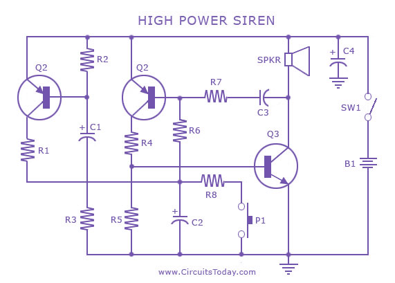
A siren circuit diagram that generates a strong, high-power siren or alarm sound using complementary transistor pairs BC 557 and BC 337, arranged as an oscillator. The described siren circuit employs a pair of complementary transistors, BC 557 (a PNP...
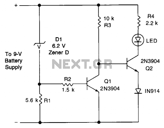
This circuit provides an early warning for battery discharge. A Zener diode (D1) is selected to indicate when the voltage falls below 9 V. If the supply voltage drops below 7 V, D1 will stop conducting, which will cause...
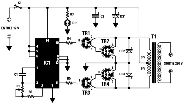
The final power transistors TR2 and TR4 must be mounted on appropriately sized heatsinks to prevent overheating. Suitable transistor options include MJ4033, MJ3007, or any other NPN type. The maximum power output is dependent on the transformer T1's core...
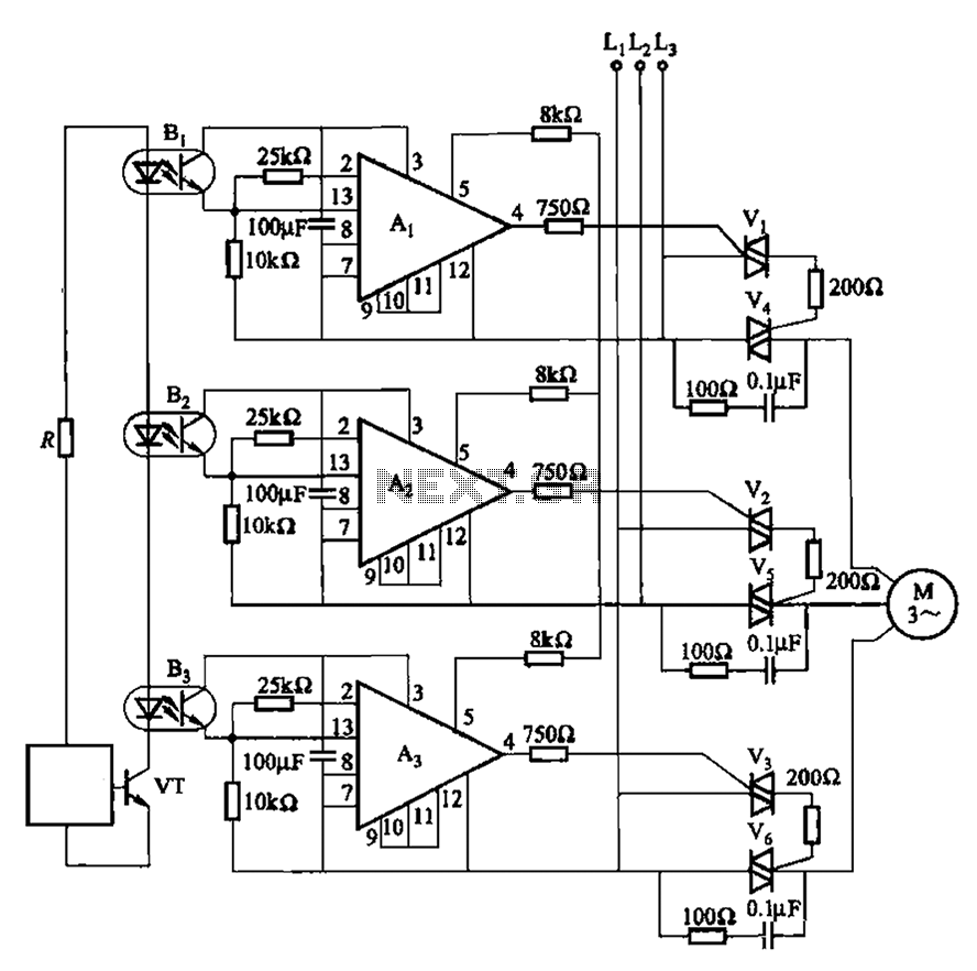
The 331 circuit depicted in the figure utilizes a two-way thyristor for controlling the start and stop functions of a motor. It operates without mechanical contacts, generating no noise or sparks, making it suitable for applications that require frequent...
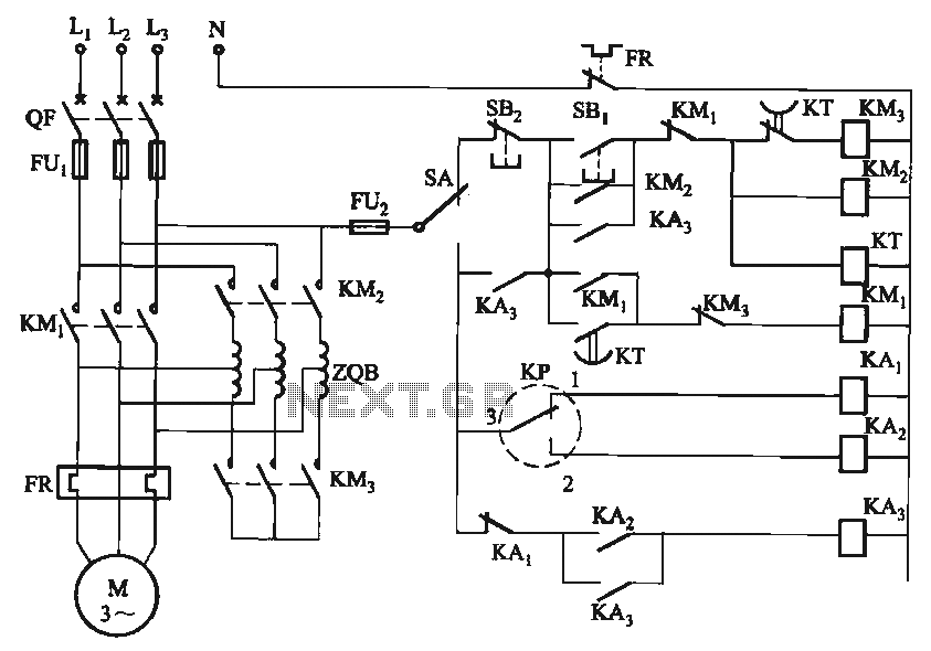
The circuit utilizes a motor auto-voltage transformer for starting. The motor auto-voltage transformer start circuit is designed to provide a controlled method for initiating the operation of an electric motor. This type of circuit is particularly beneficial in applications where...
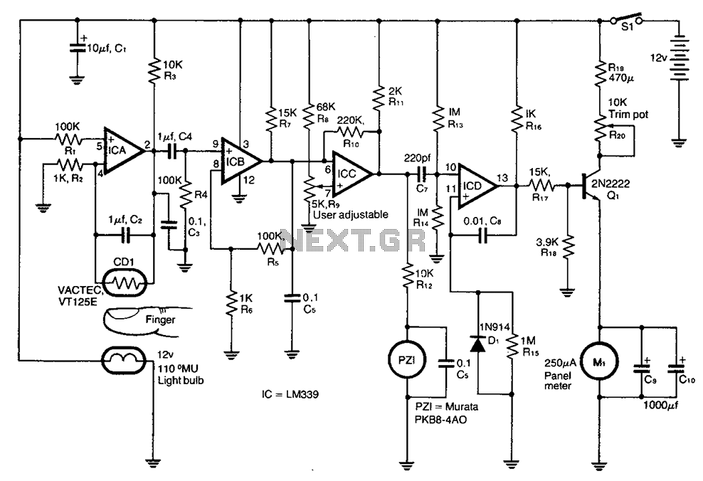
A cadmium sulfide photoresistor (CD1) fingertip can be detected through the filter. CD1 forms part of the sense amplifier feedback network. A section of the sense amplifier (ICA) produces weak signals that may be further amplified by ICB. These...