
555 timer audio alarm circuits
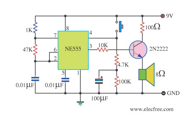
The danger beep circuit utilizes the 555 timer IC, a versatile and widely used component in electronic circuits for generating precise timing and oscillation. In this configuration, the 555 timer is set up as an astable multivibrator, which means it continuously oscillates between its high and low states, producing a square wave output.
The duty cycle of the circuit is set to 5%, meaning that the output signal remains high for only 5% of the total period and low for the remaining 95%. This low duty cycle is essential for creating a beeping sound that is both short and sharp, ideal for alerting users to potential dangers.
The circuit typically comprises several key components: the 555 timer IC, resistors, capacitors, and a loudspeaker. The resistors determine the charge and discharge times of the timing capacitor, which in turn sets the frequency of the oscillation. By selecting appropriate resistor and capacitor values, the frequency can be adjusted to achieve the desired beep rate.
The output from the 555 timer is connected to a loudspeaker, which converts the electrical signal into audible sound. The speaker's impedance must be matched to the output of the timer to ensure efficient operation. Additionally, a transistor may be included in the circuit to amplify the output signal, allowing for the use of larger speakers or higher volume levels.
Power supply considerations are also important; the 555 timer typically operates within a voltage range of 4.5V to 15V, making it compatible with various battery types or power sources. Proper decoupling capacitors should be placed near the power supply pins of the IC to filter any noise and ensure stable operation.
In summary, the danger beep circuit is an effective application of the 555 timer IC, providing a simple yet reliable means to generate a warning sound through a loudspeaker, making it suitable for various safety and alert systems.This is danger beep circuit. It use 555 integrated number circuits build to are a stable mutivibrator that be valuable duty cycle 5% driver loudspeaker.. 🔗 External reference
Related Circuits
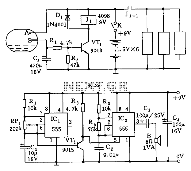
The call is triggered by the position sensing circuit, which activates the control circuit and SOS alarm circuit. This system is designed for critically ill patients or to assist disabled individuals in the event of a fall. A position...
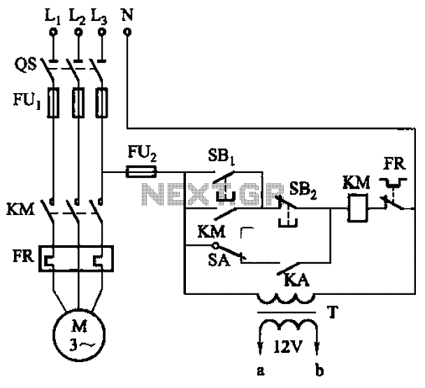
The circuit illustrated in Figure 3-81 employs a transistor delay circuit to facilitate start-stop cycle control. It can operate in both manual and automatic modes. The circuit is primarily governed by the motor run time circuit, which includes transistors...

This is a stereo audio amplifier designed for automotive applications. The circuit utilizes a single integrated circuit, the TDA1553, along with several external components. This IC is responsible for managing the stereo audio system in a vehicle. The TDA1553CQ...
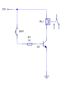
A relay is activated by grounding the low side using an NPN transistor. A pushbutton is intended to operate the transistor, thereby energizing the relay for approximately 500 milliseconds before deactivating it, while ignoring any continuous button press. Although...
This circuit includes automatic exit and entry delays along with a timed bell cut-off feature. It accommodates both normally-closed and normally-open contacts, and it has a 24-hour personal attack/tamper zone. The circuit is permanently connected to a 12-volt supply...
The 555 Stepper Pulse Generator kit will help you with the pulse required to drive your favorite DC Servo Motor application. This kit uses the famous 555 timer IC for generating the Stepping Pulse. More: Input - 5 -...