
Six a start and stop intermittent cycle control circuits
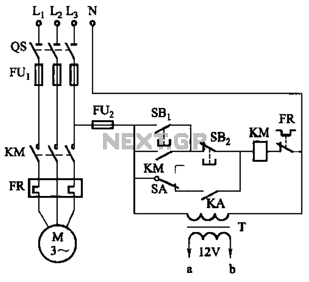
The circuit operates by utilizing a combination of transistors and FETs to manage the timing of the motor's operation. The motor run time circuit is responsible for determining how long the motor remains active during each cycle. Transistor VTi serves as the primary control element, while the FETs VTz and VTa provide additional switching capabilities to ensure efficient operation.
In parallel, the downtime control circuit is designed to manage the intervals during which the motor is inactive. This is crucial for applications that require precise timing and control over motor functions. The FET transistors VT4, VTs, and VT6 play significant roles in this aspect, allowing for rapid switching and reliable performance.
The inclusion of potentiometers RPi and RPz enables users to fine-tune the operation of the circuit. By adjusting these components, the user can extend or shorten the duration of the motor's active and inactive states, providing flexibility to meet specific operational requirements. This adaptability is particularly beneficial in applications where varying motor speeds or operational cycles are necessary.
Overall, the circuit exemplifies a sophisticated approach to motor control, leveraging the versatility of transistors and FETs to achieve efficient start-stop operations. The design ensures that both manual and automatic control options are available, making it suitable for a wide range of applications. Circuit shown in Figure 3-81. The circuit uses a transistor delay circuit to achieve start-stop cycle control. You can take the hand moving and automatic manner. Circuit is pri marily controlled by the motor run time circuit (VTi and the FET transistor VTz, VTa etc.) and downtime control circuit (the FET transistor VT4 and VTs, VT6 etc.) of two parts. Adjust potentiometer RPi and RPz, can change the motor running and stop time.
Related Circuits
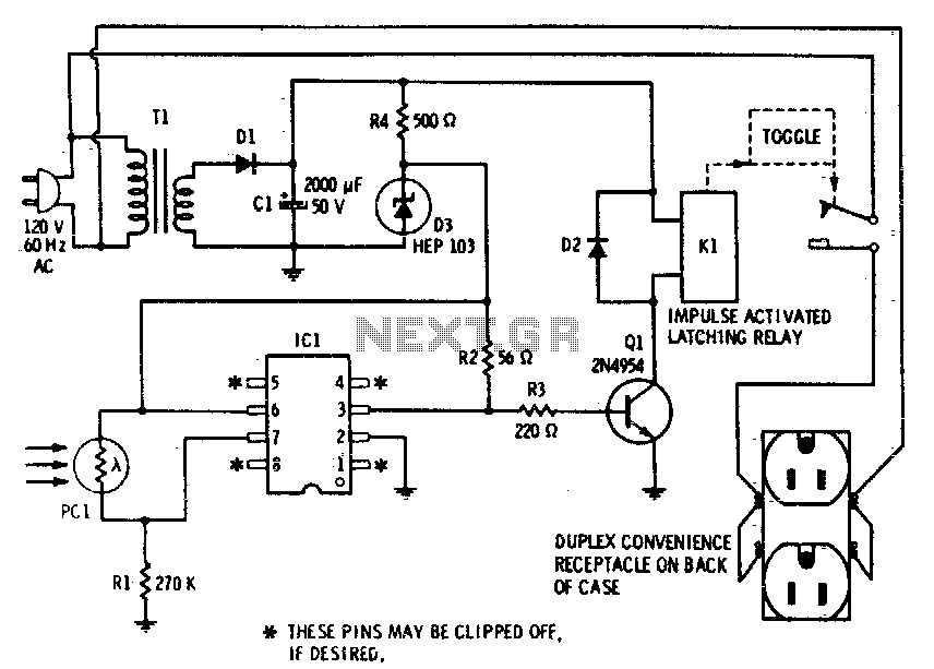
This device enables remote control of AC-powered appliances by utilizing the beam of a flashlight as a triggering mechanism. A key feature of this gadget is its memory function; activating it once supplies power to the device, and it...
This circuit is designed to create an early warning alarm system for any form of theft that is important to the owners of a motorcycle or bicycle. This alarm system can utilize a number of normally open switches, such...
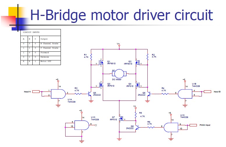
An H-bridge motor driver circuit is designed to control a DC motor. By using a low signal, such as a 5-volt signal, the circuit enables the program to manage the motor, which operates on a higher power supply. The H-bridge...
The aim of this project was to get a digital camera into a small electric radio controlled (RC) aeroplane and still have it fly. The aeroplane shown, a park flyer, weighs between 400 and 550 grams depending on the...
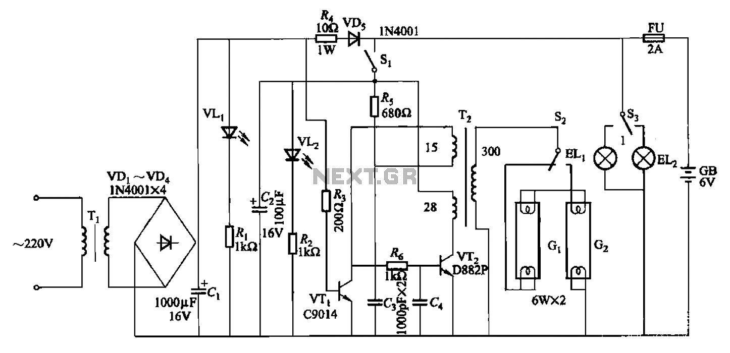
The 786A multi-functional double-tube fluorescent emergency circuit is illustrated in Figure 2-129. This circuit shares similarities with Figure 2-125. The 786A multi-functional double-tube fluorescent emergency circuit is designed to provide illumination during power outages or emergencies. It utilizes two fluorescent...
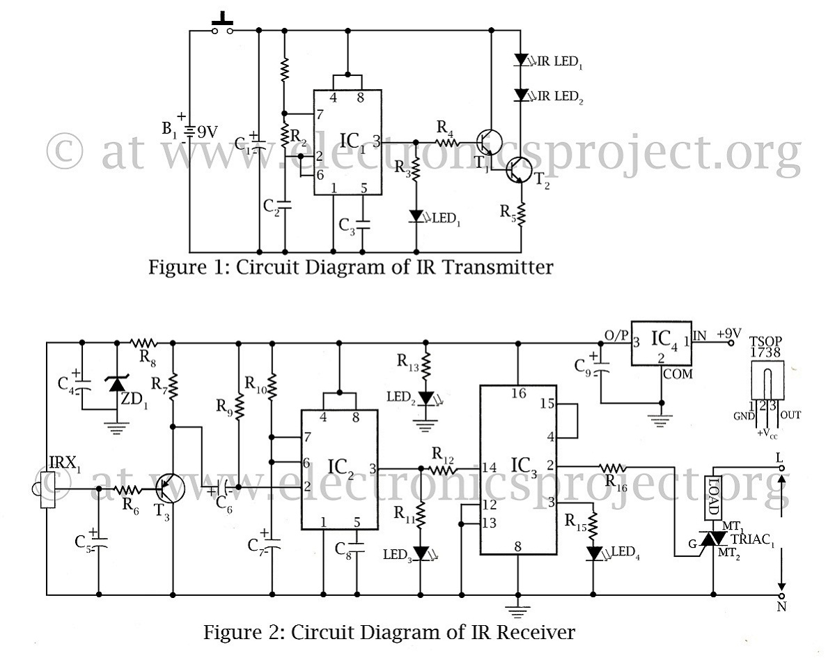
The infrared remote-controlled switch is the second remote-controlled project on this website, utilizing a 555 IC circuit diagram along with a description of the remote-controlled switch. The infrared remote-controlled switch operates using a 555 timer integrated circuit (IC), which is...
Warning: include(partials/cookie-banner.php): Failed to open stream: Permission denied in /var/www/html/nextgr/view-circuit.php on line 713
Warning: include(): Failed opening 'partials/cookie-banner.php' for inclusion (include_path='.:/usr/share/php') in /var/www/html/nextgr/view-circuit.php on line 713