
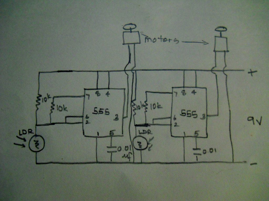
555 timer based light seeking robot
The schematic for the robot features a basic structure that integrates various electronic components to facilitate its operation. The primary elements include a microcontroller, which serves as the brain of the robot, controlling its functions and processing inputs from various sensors. The microcontroller is typically connected to power supply circuits that ensure stable operation.
Input devices such as ultrasonic sensors or infrared sensors may be included in the design to enable obstacle detection and navigation capabilities. These sensors provide real-time data to the microcontroller, allowing the robot to make informed decisions based on its environment.
The output components often consist of motors or servos that drive the robot's movement. These actuators are connected through a motor driver circuit, which can handle the current requirements of the motors and provide the necessary control signals from the microcontroller.
Power management is another critical aspect of the schematic. A voltage regulator may be used to ensure that all components receive the appropriate voltage levels, protecting sensitive components from potential damage due to overvoltage.
Connections between components are typically represented with lines on the schematic, indicating the flow of signals and power. Proper labeling of each component and clear representation of the circuit pathways are essential for understanding the robot's functionality and for troubleshooting purposes.
Overall, the schematic diagram serves as a comprehensive guide for assembling the robot, detailing the relationships between components and their individual roles in the overall system.The schematic diagram of this robot is very simple to understand. As I had mentioned earlier I just modified a circuit from on of the books to create.. 🔗 External reference
Related Circuits

This circuit provides an intermittent siren output with an automatic reset feature. It can be operated manually through a key-switch or a hidden switch, and it can also be configured to activate automatically when the ignition is turned off....
National Instruments Multisim now features microcontroller unit co-simulation capabilities, enabling the inclusion of a microcontroller, programmed in assembly or C code, within SPICE-modeled circuits. The MCU functionality in Multisim allows students, educators, and professional users to program MCUs in...
This circuit is based on the State Variable Band Pass Filter, incorporating amplitude-limited regenerative feedback. The State Variable Band Pass Filter (SVBPF) is a versatile filter design that allows for simultaneous control over the center frequency, bandwidth, and gain. This...

This circuit replicates the starting light sequence used by FISA in Formula One racing. It can be utilized with slot car sets (such as HO scale AFX, Life Like, or Tyco sets) or radio-controlled cars. The circuit employs a...
A 2001 Monte Carlo is experiencing electrical issues where only the lights are functioning. The radio, wipers, turn signals, and dash lights do not operate when the ignition key is turned. It has been suggested that the computer system...

This is vWalker v1, where "v" represents V, indicating five. It is a five-motor walker designed to move toward light while avoiding obstacles. The objective was to develop a walker capable of navigating rough and complex terrain while seeking...