
Walker Robot
The motor drivers are not depicted; instead, two sets of three 74AC240 inverters in parallel are utilized to drive each servo. Any suitable driver can be used by replacing the (M) with the driver's designation. This operational description should be referenced alongside the schematic of Ian's vWalker v1. The schematic does not display pin numbers for the 240 inverters but identifies them with a letter denoting a group of four inverters, all tri-state enabled by the same control pin. Each 74HC/AC240 chip comprises two groups of four inverters and two tri-state enable pins. Some groups are permanently enabled by grounding the control pin, while others are controlled via the tri-state enable pin for reverser and control circuits. It is common for only one or two inverters from a group of four to be utilized, leaving the others unused. This design approach, referred to as "tile" circuits, simplifies connections but may not fully leverage available resources. In this description, a group letter followed by a number in brackets identifies the number of inverters used for specific circuit components.
I) The light detector employs inverters from groups F(2), J(2), K(1), L(1), and a two-input AND gate to produce enable signals that dictate three output states: a. turn left, b. turn right, c. move straight. II) The two master bicores utilize inverters from groups B(2) and C(2), coupled with a 7.2M resistor to oscillate in quadrature, with their waveforms overlapping by 25%. These are connected to the motor drivers (Ian employed six 74AC240 inverters for each motor), which control the rear leg movement. III) The two front motor slave bicores use inverters from groups D(2) and E(2), incorporating timing components that delay the output by approximately 25%. These connect to the front leg motor drivers (six inverters for each motor). IV) The front motor reverser circuits and LED indicators utilize inverters from groups H(3) and I(3), linking the outputs of the master bicores (rear legs) to the slave bicores (front legs) to manage turning via enable signals from the light detector circuit. When both reversers are inactive, the walker proceeds straight. V) A waist slave bicore circuit employs inverters from group A(2) to control the waist motor driver (using six 240 inverters). This slave bicore may not be necessary. VI) The waist inverter uses inverters from group G(2) and connects between one output of each of the two master bicores and the waist slave bicore circuit. The output of the reverser should ideally connect directly to the waist motor drivers. The waist reverser circuit is activated by one of two tactile switches triggered by collision. VII) The power supply comprises a 4.8V NiCd battery with an on/off switch, and a rectifier is included for recharging the battery pack without removal from the walker. The light detector consists of two photodiodes configured as a "photo bridge" to detect balanced or unbalanced light levels. The two photodiodes are connected in reverse.
This comprehensive layout details the operational and functional aspects of the vWalker v1, providing a clear understanding of its design and capabilities.This is vWalker v1. The "v" standing for V, as in five. It is a five motor walker that goes towards light and avoids obstacles. The goal was to create a walker that could navigate over rough complex terrain while seeking out the brightest source of light. The base controller for the walker is four master/slave linked bicores. All of the other circ uits take input from sensors and modify the signal coming out of the bicores to make the walker backup, turn, and seek light. Currently vWalker has five possible states. Walk forward lifting the front legs Walk forward lifting the back legs Walk backwards Stray to the right ~2` turn radius Stray to the left ~2` turn radius Notes: The only thing not show are the motor drivers.
I used two sets of three 74AC240 inverters in parallel to drive each servo. Any driver will work so just swap out the (M) with your driver of choice. Here`s what mine looked like. This description of operation must be used with the schematic in of Ian`s vWalker v1. Currently this schematic shows no pin numbers for the 240 inverters but identifies the inverters with a letter as one of a group of 4 inverters which are tri-state enabled by the same control pin. Each 74HC/AC240 chip has two groups of four inverters and two tri-state enable pins. Some groups are permanently enabled by grounding the control pin. Other groups of inverters are turned on or off with the tri-state enable pin for reverser and control circuits.
In some cases, only one or two inverters of a group of four is used, while the others are left unused. This is probably a result of the use of "tile" circuits which are easy to connect together to form a functional circuit but this design method is often inefficient in making full use of the available resources.
In this description, the group letter followed by a number in brackets is used to identify and indicate the number of inverters used for a particular part of the circuit. I) The light detector uses inverters from group F(2), J(2), K(1), L(1) and one 2 input AND gate to generate the enable signals which control 3 output states: a.
turn left, b. turn right, c. go straight II) Two master bicores use inverters from groups B(2) and C(2) which are coupled with the 7. 2M resistor to so that they will oscilate in quadrature with their waveforms overlapping by 25%. These are connected to the motor drivers (Ian used 6 74AC240 inverters for each motor) which control the two rear legs.
III) Two front motor slave bicores use inverters from groups D(2) and E(2) with timing components that delay the slave bicore output by about 25%. These are connected to the front leg motor drivers (6 inverters for each motor). IV) Two front motor reverser circuits and LED indication use inverters from groups H(3), I(3) and are connected between the outputs of each of the master bicores (rear legs) and the slave bicores (front legs) to control turning with enable signals from the light detector circuit.
When both reversers are turned off, the walker moves straight. V) One waist slave bicore circuit uses inverters from group A(2) to control the waist motor driver (using six 240 inverters). In fact (as far as I know) this slave bicore is not required at all (see VI). VI) The waist inverter uses inverters from group G(2) and is connected between one output of each of the two master bicores and the waist slave bicore circuit in V).
As far as I know the output of the reverser should be connected directly to the waist motor drivers. The waist reverser circuit is enabled with one of two tactile switches triggered by collision. VII) The power supply consists of a 4. 8V NiCd battery with an on off switch and a rectifier is included for recharging the battery pack without removing it from the walker. The light detector uses two photodiodes as a "photo bridge" to sense when the light level is balanced or unbalanced on two photodiodes.
The 2 photodiodes are connected rever 🔗 External reference
Related Circuits
The advent of new high-speed technology and the growing computer capacity provided realistic opportunity for new robot controls and realization of new methods of control theory. This technical improvement together with the need for high performance robots created faster,...
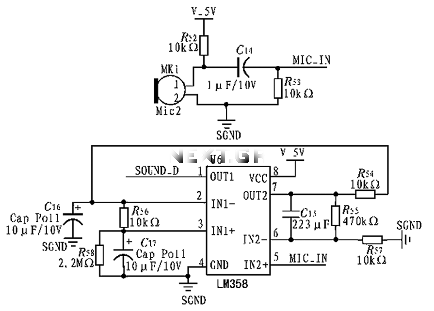
The circuit diagram focuses on the research and design features applied to mobile robots. The design considers small size, low power consumption, and ease of movement, catering to home users with a user-friendly display interface. For speech recognition, a...
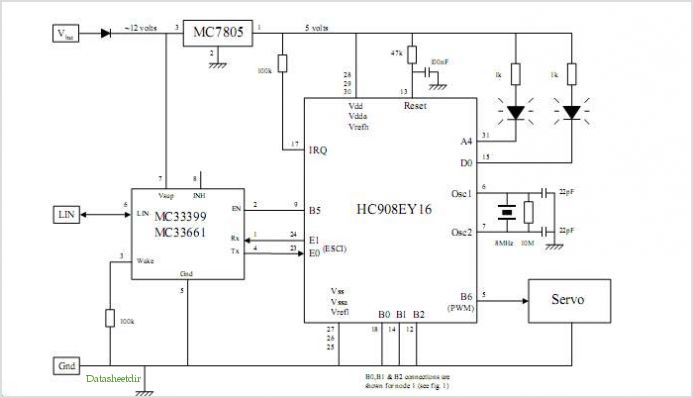
System Oscillator Crystal/Ceramic Oscillator. The following circuit combination of resistors, capacitors, and inductors depicts an equivalent circuit for a crystal or ceramic oscillator. The system oscillator, specifically a crystal or ceramic oscillator, utilizes a combination of passive components, including resistors,...
The motion games on the Nokia 5800 sparked an interest in creating a real-world version of a racing car controlled by tilting a phone. The motion-controlled robot, named Hercules due to its high torque and speed, is operated via...
The basic circuit using the L293 forms an H-Bridge driver, as shown in Figure 1, is designed for controlling inductive loads like DC motors. External diodes are necessary for suppressing back EMF. The MiniBoard utilizes the L293D, which features...
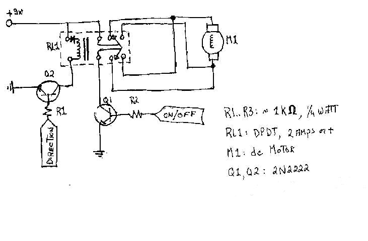
To create the circuitry described, a computer software capable of controlling a parallel port is required, with an estimated cost of approximately $30. For instance, a transistor (model number 2N2222) is priced around $0.50, while a DPDT relay costs...