
555 timer based plasma speaker
The audio-modulated plasma speaker operates by utilizing a high-voltage output from a flyback transformer to create a plasma arc that produces sound. The flyback transformer is a type of electrical transformer that generates high-voltage, low-current electricity, commonly found in CRT televisions and monitors.
To construct the plasma speaker, the following components are typically required: a flyback transformer, a suitable audio input source (such as a smartphone or computer), a driver circuit to modulate the audio signal, and safety equipment to handle the high-voltage output.
The construction begins with safely disassembling the CRT display to extract the flyback transformer. Proper precautions must be taken to avoid electric shock, as the transformer can produce voltages in the range of several kilovolts.
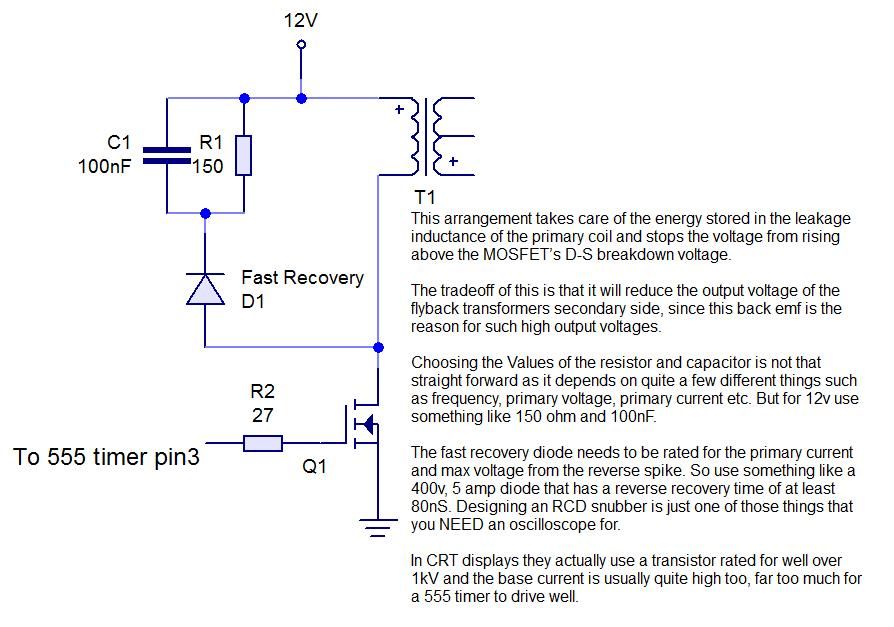
The driver circuit is designed to take the audio signal and modulate the high-voltage output from the flyback transformer. This modulation allows the plasma arc to vibrate at audio frequencies, producing sound waves that can be heard.
The audio input is connected to the driver circuit, which then drives the flyback transformer. The output from the transformer creates a visible plasma arc, and the sound generated can vary based on the frequency and amplitude of the audio input.
It is crucial to ensure that the entire assembly is housed in a secure and insulated enclosure to prevent accidental contact with the high-voltage components. Adequate ventilation is also necessary to dissipate heat generated during operation.
Overall, this project combines principles of high-voltage electronics and audio modulation to create a unique sound-producing device, demonstrating the intersection of art and engineering in a visually striking manner.This instructable will show you how to make an audio modulated plasma speaker using a flyback transformer out of an old CRT display, and the all time.. 🔗 External reference
Related Circuits
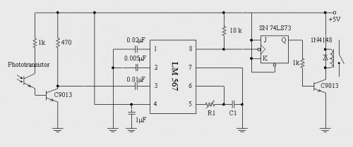
A simple circuit diagram illustrates a schematic for a remote control system, which consists of two parts: the transmitter and the receiver. The transmitter circuit is controlled by an NE555 integrated circuit (IC) and operates by detecting the emitted...
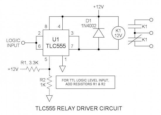
Many integrated circuits possess undocumented features or capabilities. One such example is the TLC555, which can sink a 100mA load down to 1.28V at its output (pin 3). The open-drain transistor reset (pin 7) can also sink 100mA to...
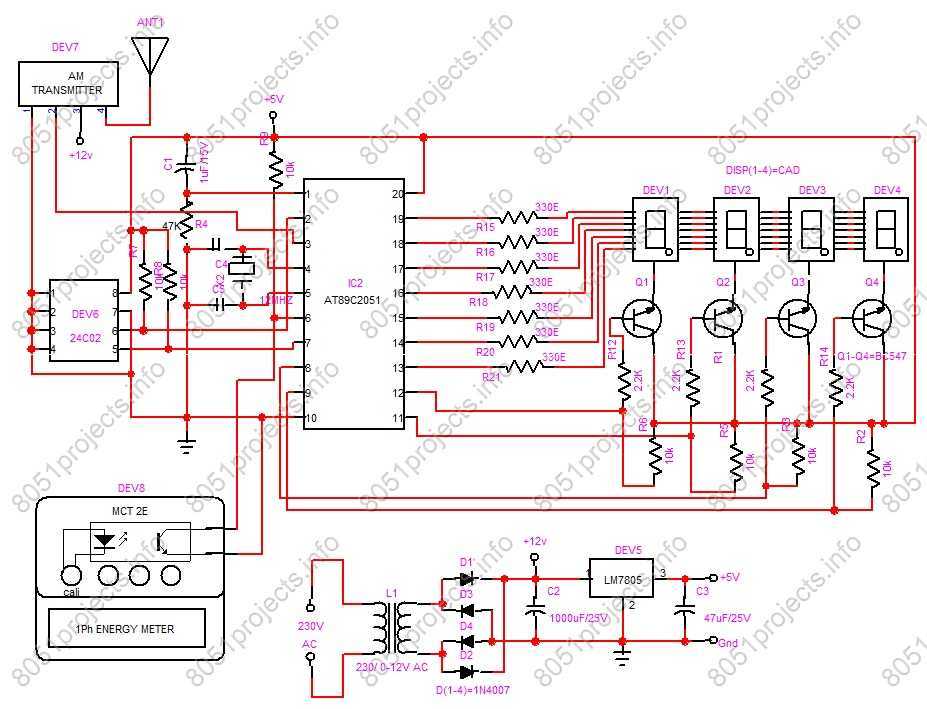
RF based Automatic meter reading, or AMR, is the technology of automatically collecting data from energy meter and transferring that data to a central database for billing and/or analyzing. This means that billing can be based on actual consumption...
555 Timer Sound Effects Videos 1. This project involves creating a light theremin using a 555 timer. It is suitable for spooky Halloween effects. 3. A film countdown timer is included. 4. A UHD chessboard timer is also featured....

This circuit is a voltage-controlled oscillator (VCO) that utilizes the 555 timer integrated circuit (IC) as its primary component. The 555 timer is configured as an astable multivibrator, enabling it to function as an oscillator. An astable multivibrator is...
In a stereo system, it is often important to determine whether the speakers are polarized. This can be especially problematic if the speaker cables lack polarity markings. The circuit described will assist in identifying the correct terminals for the...
Warning: include(partials/cookie-banner.php): Failed to open stream: Permission denied in /var/www/html/nextgr/view-circuit.php on line 713
Warning: include(): Failed opening 'partials/cookie-banner.php' for inclusion (include_path='.:/usr/share/php') in /var/www/html/nextgr/view-circuit.php on line 713