
555 tlc555 relay driver circuit
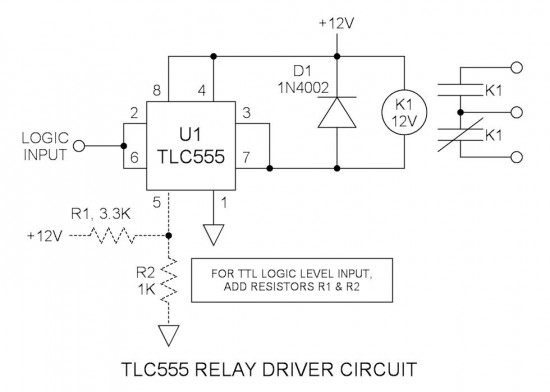
The TLC555 timer IC is a versatile device commonly used in various applications due to its ability to function as a timer, pulse generator, or oscillator. In this particular configuration, the focus is on its current sinking capabilities, which are crucial for driving inductive loads such as relay coils. The output pin (pin 3) is designed to handle a maximum sink current of 100mA, making it suitable for controlling moderate loads. By tying the reset pin (pin 7) to the output, the effective sink current can be increased to 200mA, allowing for the reliable operation of a 133mA relay coil without exceeding the IC's specifications.
The relay selected for this application is a 40A automotive relay, which is designed to handle higher current loads typically associated with automotive applications. This relay is activated by the output from the TLC555, ensuring that the relay coil is energized properly. The choice of a relay over a contactor is based on the specific current requirements of the application, where relays are generally used for lower current applications, while contactors are employed for higher current scenarios.
The configuration of the TLC555 includes a Schmitt trigger arrangement, achieved by tying the trigger input (pin 2) and threshold input (pin 6) together. This setup provides a hysteresis effect, allowing the circuit to avoid false triggering due to noise or fluctuations in the input signal. The defined upper and lower threshold voltages (8V and 4V) create a stable switching point, which is critical for reliable operation in digital logic applications.
For interfacing with 4000 series CMOS logic, the circuit is designed to accommodate TTL logic levels through the addition of two resistors. This adjustment modifies the internal voltage divider, ensuring that the input levels are compatible with standard TTL logic thresholds of approximately 1.4V and 2.8V. This adaptability enhances the versatility of the TLC555 in various digital applications, allowing it to function seamlessly alongside different logic families.
In summary, the TLC555 timer IC provides a robust solution for driving relay coils in applications requiring reliable current sinking capabilities. Its ability to operate with both CMOS and TTL logic levels, combined with its enhanced current handling through strategic pin connections, makes it an excellent choice for a variety of electronic control circuits.Many integrated circuits have undocumented features or abilities. This is one of them. The TLC555 output (pin 3) can sink a 100mA load to 1. 28V. The open drain transistor reset (pin 7) can sink 100mA to 1V. Tying both lines together is permissible because they are logically the same polarity and this potentially doubles the sink current ability to 200mA. This is ideal for driving my 133mA relay coil. While it can be seen that the NE555 has the higher current rating, its saturation voltage is grossly inferior and this is a detriment in driving loads without excessive voltage drop. Also it can be seen that the TLC555 is much like TTL in that its sourcing ability is far less than its sinking ability.
However for driving a relay, we are interested only in current sinking properties. This is a 40A automotive relay (contactor) that I selected for this application. Since its coil current exceeds the TLC555 output sink current rating, it is a good candidate. Manufacturer or part number is unknown. What is the difference between a relay and a contactor There is no clear difference other than perhaps current rating and/or application ”to me, relays are anything from signal devices to approx 20A. Anything rated at 40A or larger, or is used in power applications is a contactor. The trigger input (pin 2) and the threshold input (pin 6) pins are tied together ”this is commonly done.
With a 12V supply, the upper threshold is 8V and the lower is 4V. The two voltage levels, being far apart, make a great Schmitt trigger. This may be driven directly by 4000series CMOS logic that is also powered via 12V. To make it compatible with TTL logic levels, simply add the two resistors that are shown in the schematic. This loads down the internal divider to a lower voltage. The calculated levels are approx. 1. 4 and 2. 8V respectively. 🔗 External reference
Related Circuits
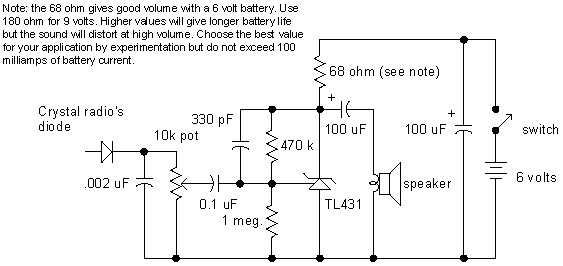
A simple audio amplifier application using a TL431 voltage regulator. The amplifier is designed to produce room-filling sound from a standard clear radio equipped with a long-wire antenna and suitable ground. The chip is similar in complexity to a...
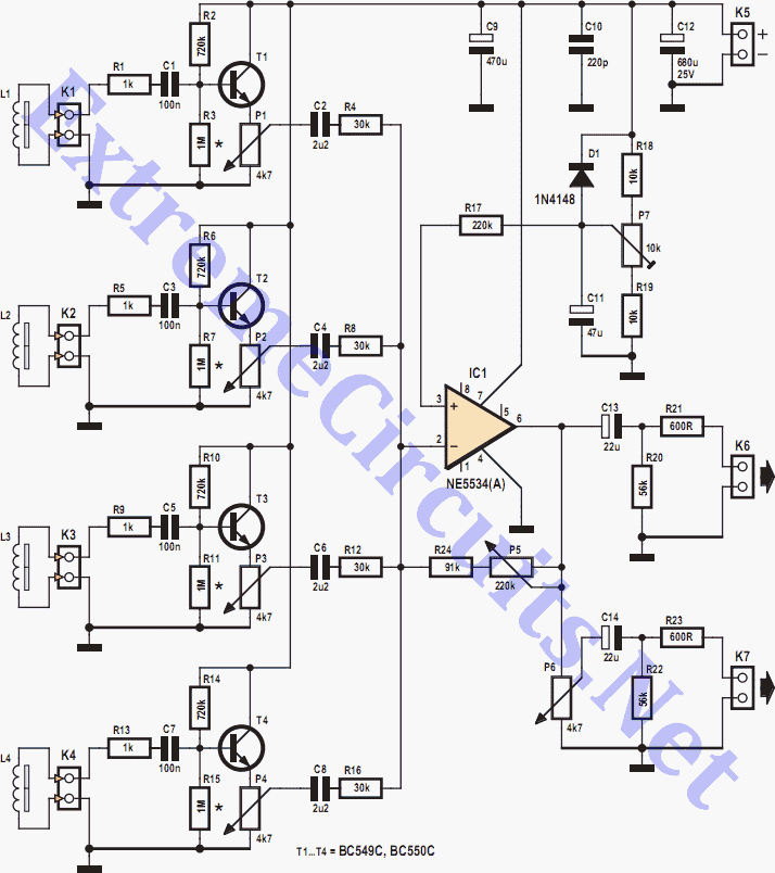
Depending on its design, an electric guitar may have anywhere from one to six pickup elements. Classic acoustic guitars can also benefit from one or more retrofitted pickups. Each pickup produces a specific sound based on the type of...
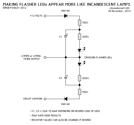
This circuit when used with a 555 timer will cause light emitting diodes to turn on and off more slowly. This will make the LEDs appear similar to incandescent lamps. The described circuit utilizes a 555 timer IC configured in...
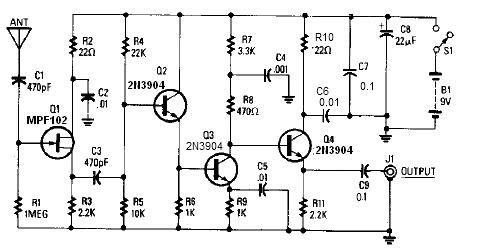
A simple active antenna can be designed using this electronic circuit diagram. This active antenna utilizes transistors and a few common electronic components. In the practice of short-wave frequency reception, a general rule is that a longer antenna will...
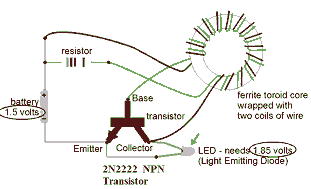
This circuit is known as the Joule Thief. For those unfamiliar with it, an image of the circuit is provided. The Joule Thief is a minimalist circuit designed to extract usable voltage from a low-voltage power source, such as a...
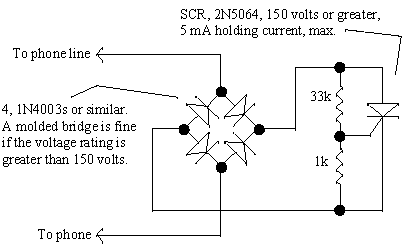
When a new computer modem is introduced into a home, the demand on the phone line increases significantly. Internet users can consume phone time similarly to a chatty teenager. Additionally, computer modem users often prioritize their privacy; for instance,...