
555 timer IC as A-stable Multivibrator
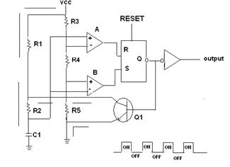
The astable multivibrator configuration of the 555 timer IC operates continuously in a square wave output mode, making it suitable for generating clock pulses or timing applications. In this setup, the timer does not have a stable state; it oscillates between high and low states by charging and discharging the timing capacitor (C1) through the resistors (R1 and R2).
The circuit operates as follows: When power is applied, the capacitor C1 begins to charge through resistors R1 and R2. The voltage across C1 rises until it reaches the threshold voltage (2/3 Vcc), at which point the output at Pin 3 switches from high to low. This transition causes C1 to discharge through R2 until the voltage drops to the trigger level (1/3 Vcc), at which point the output switches back to high, and the cycle repeats.
The frequency of oscillation (f) and the duty cycle (D) of the output waveform can be calculated using the following formulas:
1. Frequency (f) = 1.44 / ((R1 + 2R2) * C1)
2. Duty Cycle (D) = (R2 / (R1 + 2R2)) * 100%
These equations indicate that by adjusting the values of R1, R2, and C1, the frequency and duty cycle of the output waveform can be precisely controlled, allowing for versatile applications in timers, pulse-width modulation, and tone generation circuits.
In practical applications, the 555 timer IC is widely used in various electronic devices, including LED flashers, tone generators, and frequency modulators, due to its reliability and ease of use. Proper selection of the timing components is crucial for achieving the desired performance in specific applications.A 555 timer IC is used a a-stable multivibrator as shown in the given figure (A). The threshold input is now connected to the trigger input (Pin 2), the resister R1, R2 and capacitor C1 for timing network which set the frequency of the oscillator.. 🔗 External reference
Related Circuits
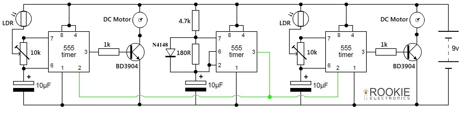
This is a simple and cost-effective approach to a line-following robot. It does not utilize any microcontroller but instead relies on a basic circuit composed of three 555 timers. The robot demonstrates good efficiency in following various curves and...
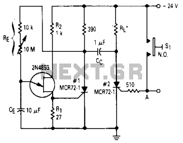
After one cycle of operation, SCR1 will be activated, resulting in a low voltage being applied to the UJT emitter circuit, which interrupts the tuning function. When pushbutton SI is pressed, or a positive pulse is applied at point...
The signal emitted by an IR remote control contains two parts, the control pulses and a modulated carrier wave. The control pulses are used to modulate the carrier, a popular modulation frequency being 36 and 42KHz. The signal is...
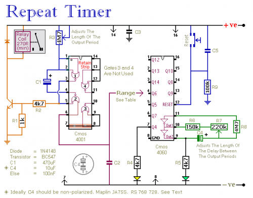
This circuit features an adjustable output timer capable of re-triggering at regular intervals. The output duration can range from a fraction of a second to half an hour or longer, with the ability to recur at intervals spanning from...
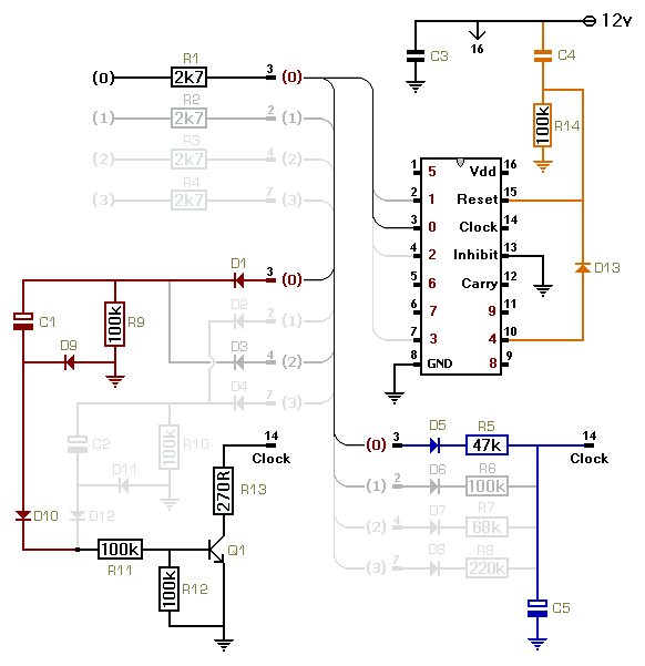
This circuit utilizes a CMOS 4017 decade counter, which begins counting from zero and increments by one each time pin 14 is activated. Upon reaching a count of nine, it resets to zero and starts the counting process again....
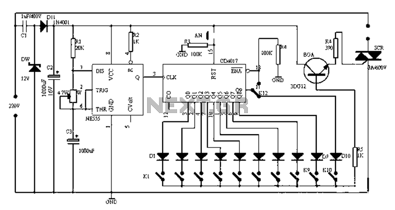
Figure 1-1 illustrates a general-purpose timer capable of timing intervals ranging from 5 minutes to 18 hours. The timing cycle can be adjusted to span from 5 minutes to 20 hours, with a maximum control time of 18 hours....
Warning: include(partials/cookie-banner.php): Failed to open stream: Permission denied in /var/www/html/nextgr/view-circuit.php on line 713
Warning: include(): Failed opening 'partials/cookie-banner.php' for inclusion (include_path='.:/usr/share/php') in /var/www/html/nextgr/view-circuit.php on line 713