
Timer circuit

The described circuit employs two Silicon Controlled Rectifiers (SCRs) and a Unijunction Transistor (UJT) for timing and control applications. The operation begins with SCR1 being triggered, which connects the UJT emitter circuit to a low voltage. This condition effectively halts any tuning function that may be in progress.
The circuit includes a pushbutton switch (SI) that functions as a manual reset or trigger mechanism. When SI is pressed, or when a positive pulse is applied to point A, SCR2 is activated. This action simultaneously turns off SCR1 through the commutation process facilitated by capacitor CC. As SCR1 turns off, the circuit re-establishes the supply voltage to the resistor RE, thus restarting the timing sequence.
The timing interval is governed by the charge time of capacitor CC, which is influenced by the resistance value of RE. As the capacitor charges, the UJT will eventually reach its firing threshold, at which point it will turn SCR1 back on and turn off SCR2. This cycle of operation can be repeated, allowing the circuit to function as a timer or oscillator depending on the configuration of the components involved.
In summary, this circuit provides a reliable method of timing control using SCRs and a UJT, with the timing duration adjustable via the resistor RE. The interaction between the SCRs and the capacitor is crucial for achieving the desired timing characteristics, making this circuit suitable for various timing applications in electronic systems.After one cycle of operation, SCR 1 will be on, and a low value of voltage is applied to the UJT emitter circuit, interrupting the tuning function. When pushbutton SI is pushed, or a positive going pulse is applied at point A, SCR 2 will turn on, and SCR 1 will be turned off by commutating capacitor CC.
With SCR 1 off, the supply voltage will be applied to RE and the circuit will begin timing again. After a period of time determined byihe setting of RE, the UJT will fire and turn SCR 1 on and commutate SCR 2 off. The time delay is determined by the charge time of the capacitor.
Related Circuits
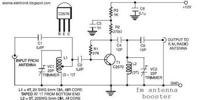
The coil L2 is tapped at the first turn from the ground lead side and is similar to coil L1, but consists of only three turns. The pin configuration of the transistor 2SC2570 is illustrated in the FM antenna...
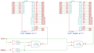
The memory component of the Mark 2 system is quite straightforward. It consists of two 32K SRAM chips, which are actually FRAM due to availability, but this does not impact functionality in this context. The selection of these chips...
Four simple 12V power supply circuits are designed to provide output voltages close to 12V. The first power supply circuit utilizes a BD139 transistor, a zener diode, and several passive components. Each schematic is straightforward to assemble and will...
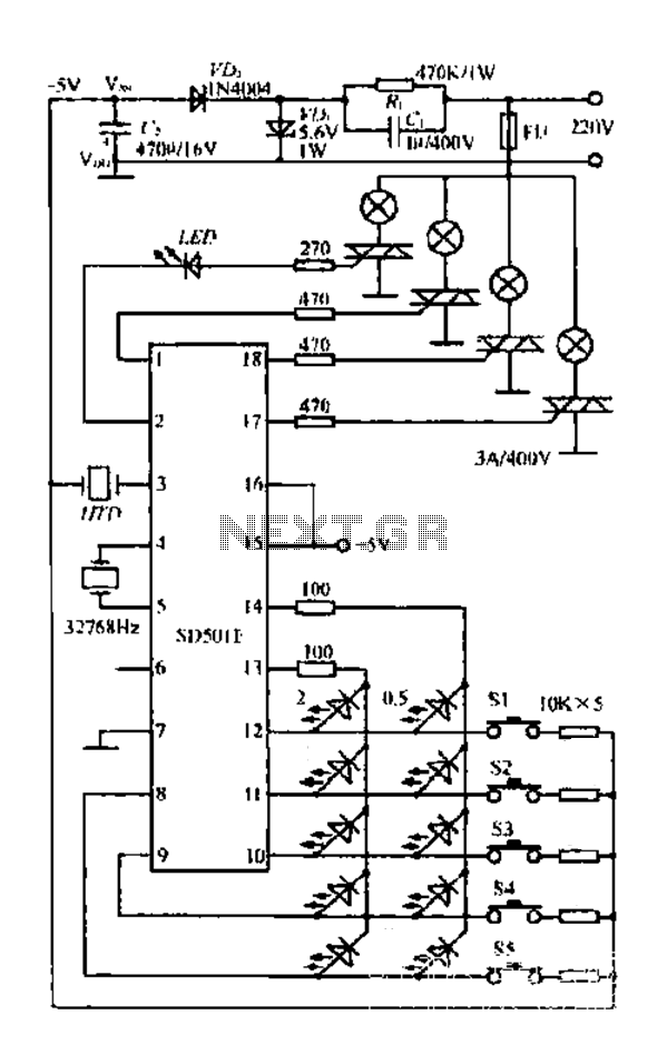
The FIG SD501E is a J tie fan integrated circuit (IC) characterized by progressive timing and three operational modes: strong, medium, and weak. It features three types of output settings and includes an electrical swing mechanism. The device is...
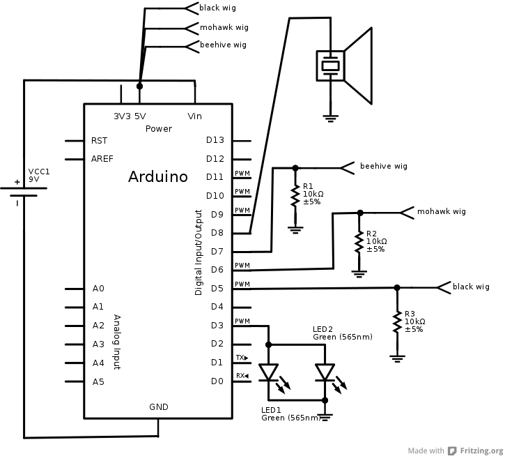
The interaction design for the singing pig was to have a different song start playing when a different wig is placed on the pig. The pig needed to stand by itself without being connected to anything else, and the...
Face Through attendance is the world's first embedded facial recognition machine, with an error rate of less than one in one hundred thousand and a rejection rate of less than one percent. In the field of biometrics, this device...