
60 Watt MosFet Audio Amplifier

This circuit represents a 60 to 90W high-quality power amplifier design, intended to exceed the performance specifications of a previous 25W MosFet amplifier. The circuit topology is similar to that of the earlier design, but utilizes robust IRFP240 and IRFP9240 MosFet devices as the output pair. High-voltage Motorola transistors are employed in the preceding stages to enhance performance. The supply rail voltage is conservatively set at ±40V, though it can be increased to a maximum of ±50V for those looking to achieve closer to the 100W output target into an 8-ohm load.
In the original circuit configuration, a series of three diodes was connected to R10. To improve quiescent current stability across a broader temperature range, two of these diodes have been replaced with a red LED, as suggested by David Edwards of LedeAudio.
The values specified for C1 and C2 in the Power Supply Parts List are the minimum required for mono amplifier operation. For optimal performance in stereo configurations, it is recommended to increase these capacitance values to 10,000 µF as a suitable compromise.
Proper grounding is critical for minimizing hum and preventing ground loops. It is advisable to connect the ground sides of resistors R1, R3, capacitors C2, C3, and C4, along with the ground input wire, to a common point. Additionally, R7 and C7 should be connected to C11, which in turn connects to the output ground. Input and output grounds should be separately connected to the power supply ground to ensure effective noise reduction and stable operation.R1_47K 1/4W Resistor R2_4K7 1/4W Resistor R3_22K 1/4W Resistor R4_1K 1/4W Resistor R5, R12, R13_330R 1/4W Resistors R6_1K5 1/4W Resistor R7_15K 1/4W Resistor R8_33K 1/4W Resistor R9_150K 1/4W Resistor R10_500R 1/2W Trimmer Cermet R11_39R 1/4W Resistor R14, R15_R33 2. 5W Resistors R16_10R 2. 5W Resistor R17_R22 5W Resistor (wirewound) C1_470nF 63V Polye ster Capacitor C2_470pF 63V Polystyrene or ceramic Capacitor C3_47 µF 63V Electrolytic Capacitor C4, C8, C9, C11_100nF 63V Polyester Capacitors C5_10pF 63V Polystyrene or ceramic Capacitor C6_1 µF 63V Polyester Capacitor C7, C10_100 µF 63V Electrolytic Capacitors D1_1N4002 100V 1A Diode D2_5mm. Red LED Q1, Q2, Q4_MPSA43 200V 500mA NPN Transistors Q3, Q5_BC546 65V 100mA NPN Transistors Q6_MJE340 200V 500mA NPN Transistor Q7_MJE350 200V 500mA PNP Transistor Q8_IRFP240 200V 20A N-Channel Hexfet Transistor Q9_IRFP9240 200V 12A P-Channel Hexfet Transistor R1_3K9 1W Resistor C1, C2_4700 µF 63V Electrolytic Capacitors (See Notes) C3, C4_100nF 63V Polyester Capacitors D1_400V 8A Diode bridge D2_5mm.
Red LED F1, F2_4A Fuses with sockets T1_230V or 115V Primary, 30+30V Secondary 160VA Mains transformer PL1_Male Mains plug SW1_SPST Mains switch To celebrate the hundredth design posted to this website, and to fulfil the requests of many correspondents wanting an amplifier more powerful than the 25W MosFet, a 60 90W High Quality power amplifier design is presented here. Circuit topology is about the same of the above mentioned amplifier, but the extremely rugged IRFP240 and IRFP9240 MosFet devices are used as the output pair, and well renowned high voltage Motorola`s transistors are employed in the preceding stages.
The supply rails voltage was kept prudentially at the rather low value of + and 40V. For those wishing to experiment, the supply rails voltage could be raised to + and 50V maximum, allowing the amplifier to approach the 100W into 8 Ohm target: enjoy! In the original circuit, a three-diode string was wired in series to R10. Two of these diodes are now replaced by a red LED in order to achieve improved quiescent current stability over a larger temperature range.
Thanks to David Edwards of LedeAudio for this suggestion. The value suggested for C1 and C2 in the Power Supply Parts List is the minimum required for a mono amplifier. For optimum performance and in stereo configurations, this value should be increased: 10000 µF is a good compromise.
A correct grounding is very important to eliminate hum and ground loops. Connect to the same point the ground sides of R1, R3, C2, C3 and C4 and the ground input wire. Connect R7 and C7 to C11 to output ground. Then connect separately the input and output grounds to the power supply ground. 🔗 External reference
Related Circuits
This circuit is a class AB stereo audio power amplifier designed by Quasar for high-fidelity applications using a TDA2005 module. It is straightforward to construct and requires a minimal number of external components. The module includes output current protection...
When there is a need to amplify audio signals from various sources before they reach a custom amplifier, a preamplifier (or preamp) is typically employed. This document suggests a specific circuit that is interesting due to its use of...
This preamp is very simple, and will work under tough conditions. The input impedance is pretty high, so it won't load down electric guitars. It will also amplify microphones. When there is a moment, there will be some additions that...
You can use this powerful amplifier in any small audio project. It is very small (6.5 x 4.5 cm). It outputs 10W and uses a 9V battery. More: Components List R1: 6 Ohm R2: 220 Ohm R3: nothing R4:...
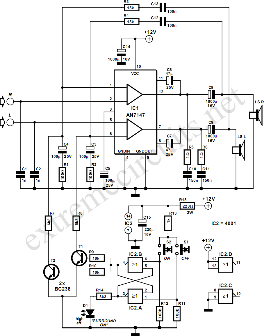
The AN7147 Dual 5.3-watt Audio Power Amplifier from Panasonic is categorized as a replacement type, indicating its anticipated availability in the market for an extended period. When combined with additional components, it can be configured to create a simple...
Incorporate resistors in a parallel configuration to enhance audio input. To control the volume for each input channel, integrate a linear trimmer or potentiometer with the following configuration: pin 1 connects to ground, pin 2 serves as the output,...