
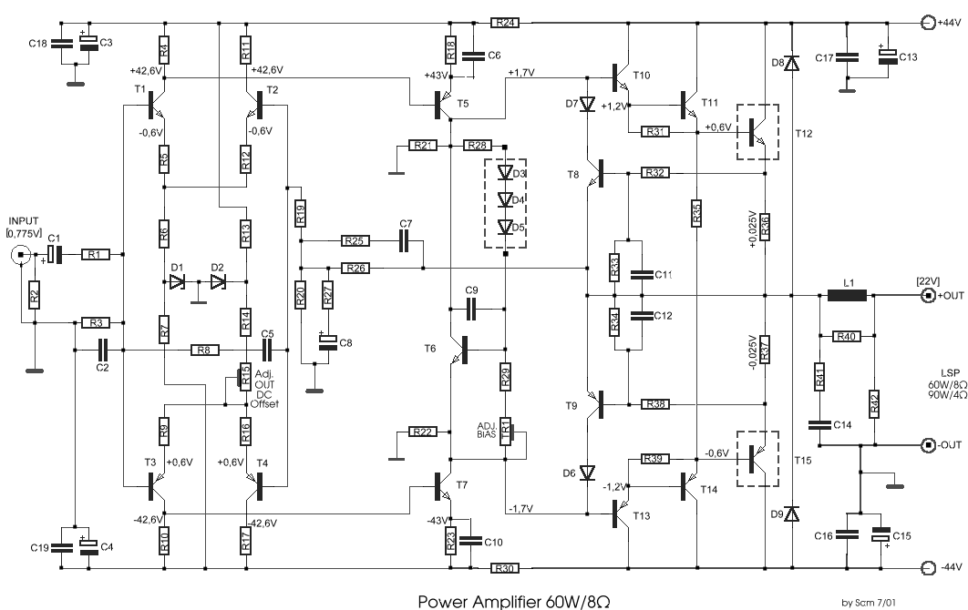
60w amplifier mosfet irfp240
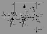
The circuit design incorporates a dual power supply configuration with positive and negative voltage rails to provide the necessary operating conditions for the amplifier. The nominal voltages of +40V and -40V are chosen to ensure stability and reliability during operation, minimizing the risk of component stress and overheating. This conservative approach helps to maintain the integrity of the amplifier's performance across various operating conditions.
For experimental purposes, an adjustment to the supply voltage can be made, allowing the rails to be increased to +50V and -50V. This adjustment is significant as it permits the amplifier to deliver up to 100W of output power into an 8 Ohm load. The increased voltage enhances the headroom of the amplifier, allowing for greater dynamic range and improved transient response, which is critical for high-fidelity audio applications.
It is important to note that when increasing the supply voltage, careful consideration must be given to the ratings of all components within the circuit, including the output transistors, power supply capacitors, and any protection circuitry. Components must be rated to handle the increased voltage and power levels to prevent failure and ensure safety during operation.
Additionally, thermal management becomes increasingly important as power levels rise. Adequate heat sinking and possibly forced air cooling may be required to dissipate the additional heat generated by the output stage at higher voltages. Overall, the design allows for flexibility in experimentation while prioritizing safety and performance integrity in the amplifier circuit.The supply rails prudentially voltage was kept at the rather low value of + and - 40V. For those wishing to experiment, the supply voltage rails could be raised to + and - 50V maximum, allowing the amplifier to approach the 100W into 8 Ohm target. 🔗 External reference
Related Circuits
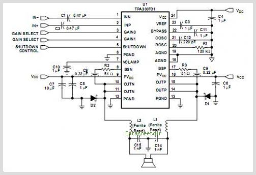
The TPA3112D1 is a 25-W efficient Class-D audio power amplifier designed for driving a bridge-tied speaker. It incorporates advanced EMI suppression technology, allowing the use of cost-effective ferrite bead filters at the outputs while complying with EMC requirements. The...
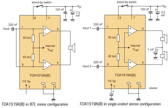
The audio amplifier circuit is based on the TDA1519 amplifier IC, which is designed for audio applications. The TDA1519 has a power output range of 2 to 6 watts. This amplifier is a Class B dual-output type and comes...
This circuit is mainly intended to provide common home stereo amplifiers with a microphone input. The battery supply is a good compromise: in this manner the input circuit is free from mains low frequency hum pick-up and connection to...
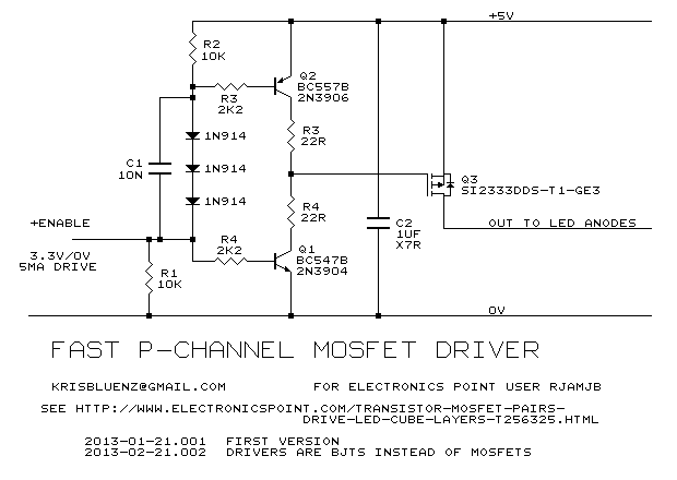
None of those devices is very suitable. The drivers aren't specified to operate with 3.3V gate signals, and although the typical graph shows that a... The devices referenced in the original input are not appropriate for the intended application due...
This circuit was designed and manufactured in the 1980s. Since then, it has operated without issues. There are no significant constructional challenges, aside from the usual considerations: ensuring the appropriate power supply voltage, selecting a suitable heatsink, and properly...
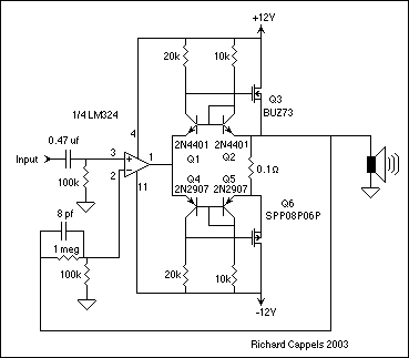
The EDFET drives like a FET, but with the bias stability of bipolar. Amps of output current can be controlled by milliamps of input current. The current gain is a design choice dictated by bandwidth. Two of things you...