
60W audio amplifier
Part List
R1=1.5Kohm R21=10ohm 1W D1=5V6 0.4W zener
R2-9=10Kohm R22-23-24-25=0.47ohm 5W Q1-2-3=BC557
R3=2.7Kohm TR1=100ohm trimmer Q4-8=BD140
R4=5.6Kohm TR2=470ohm trimmer Q5-7=BD139
R5=3.3Kohm C1=2.2uF 100V MKT Q6=BC549
R6-12=470ohm C2=330pF Q9-10=TIP2955 [MJE2955]
R7-11=1.2Kohm C3=100uF 16V Q11-12=TIP3055 [MJ3055]
R8=560ohm C4=100pF
R10=220ohm C5=27pF F1-2= 3A slow Fuse 5X20mm
R13-14=47ohm C6=3.3nF 100V MKT
R15-16=33ohm 1W C7-8-9-10-13-14=100nF 100V MKT All resistors are 1/2W 1% metal film except where noted differently
R17-18-19-20=220ohm 1W C11-12=220uF 63V
The described power amplifier circuit is designed to provide a robust output suitable for driving speakers in various applications, particularly in home cinema systems. The amplifier can deliver 60W into an 8-ohm load and 80W into a 4-ohm load, making it versatile for different speaker configurations.
The circuit utilizes a differential amplifier configuration with matched transistors Q1 and Q2, which ensures good linearity and minimal distortion. The use of trimmer potentiometers TR1 and TR2 allows for precise control of the output DC voltage and the bias current of the output stage, respectively. The recommended bias current of approximately 50mA is crucial for optimal performance and thermal stability of the output transistors.
Proper thermal management is emphasized, with transistors Q6 to Q12 requiring adequate heatsinking to prevent overheating during operation. It is important to ensure that these components are insulated from the heatsink to avoid short circuits, which could lead to circuit failure.
The circuit components are readily available, with a mix of standard resistors, capacitors, and transistors that can be sourced easily. The use of 1% metal film resistors contributes to the overall performance by minimizing noise and improving accuracy in the circuit's operation. The inclusion of a fuse (F1-2) provides an additional safety measure, protecting the circuit from overload conditions.
Overall, this power amplifier circuit is well-suited for audio applications, providing a balance of power, efficiency, and reliability. Regular monitoring and adjustments of the bias current are recommended to maintain optimal performance over time. In the circuit exist a simple power amplifier 60W in the 8 ohm and 80W in the 4 ohm, with components that sure exist in big quantities. It can be used in home cinema systems or in other uses. With the TR1 we regulate the DC voltage in the output of amplifier in low levels [±20 until ±50mV it is a good level].
Good also they are the two transistors Q1-2 of differential amplifier, they have matched characteristically. With the TR2 trimmer we regulate the transistors bias current of output power stage, in 50mA roughly for each sector.
This regulation become without exist signal in the input, place a digital multimeter in terminal since of the resistors R22-23-24-25 and regulating him TR2 should we have clue, roughly 25mV DC, that corresponds in current 50mA. We leave the amplifier to work for few hour and if it needs we regulate again. Transistors Q6 until Q12, should be placed on a good heatsink, with attention so that insulation well from the heatsink and the support screws. Part List R1=1.5Kohm R21=10ohm 1W D1=5V6 0.4W zener R2-9=10Kohm R22-23-24-25=0.47ohm 5W Q1-2-3=BC557 R3=2.7Kohm TR1=100ohm trimmer Q4-8=BD140 R4=5.6Kohm TR2=470ohm trimmer Q5-7=BD139 R5=3.3Kohm C1=2.2uF 100V MKT Q6=BC549 R6-12=470ohm C2=330pF Q9-10=TIP2955 [MJE2955] R7-11=1.2Kohm C3=100uF 16V Q11-12=TIP3055 [MJ3055] R8=560ohm C4=100pF R10=220ohm C5=27pF F1-2= 3A slow Fuse 5X20mm R13-14=47ohm C6=3.3nF 100V MKT R15-16=33ohm 1W C7-8-9-10-13-14=100nF 100V MKT All resistors is 1/2W 1% metal film except for announce differently R17-18-19-20=220ohm 1W C11-12=220uF 63V
🔗 External reference
Related Circuits
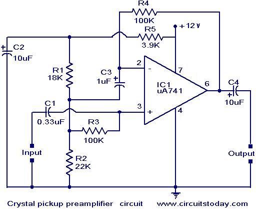
A preamplifier that operates on a single supply and is suitable for high-impedance crystal pickups is presented here. The circuit functions as a non-inverting AC amplifier, with the gain determined by the feedback resistor R4; a smaller R4 results...
The circuit incorporates an audio transformer. There is an ongoing effort to understand the concept of impedance and its significance. Clarification is sought on the necessity of an audio transformer and its function in changing impedance. An inquiry is...
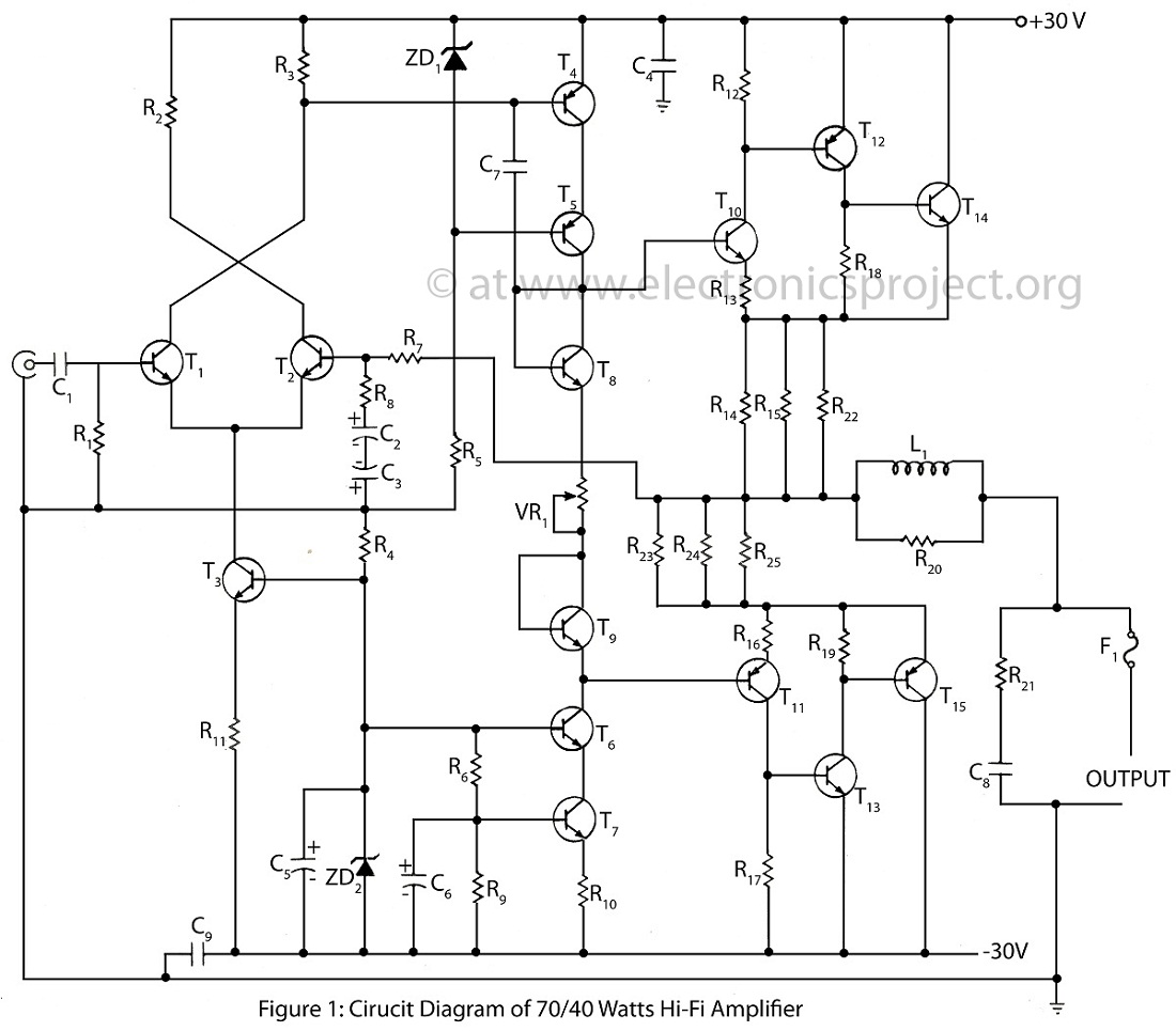
The 70/40 Watts Hi-Fi amplifier is an advanced and high-quality audio amplifier that features an almost 0% distortion circuit design. This amplifier is renowned for its exceptional sound quality and performance. The 70/40 Watts Hi-Fi amplifier utilizes a sophisticated circuit...
The TDA 2030 audio amplifier is capable of delivering 20 W of output power; however, in this schematic, the output power has been reduced to 8 W, and 10 W speakers are utilized. The input sensitivity is approximately 200...
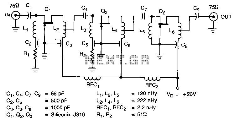
The amplifier circuit is designed for a 225 MHz center frequency, with a 1 dB bandwidth of 50 MHz, low input VSWR in a 75-ohm system, and a gain of 24 dB. Three stages of U310 FETs are utilized...

This is a circuit for an audio frequency meter. This circuit utilizes a 555 IC configured as a monostable multivibrator (one-shot trigger). A monostable multivibrator can function as a frequency-to-voltage converter by producing a fixed pulse width, with the...
Warning: include(partials/cookie-banner.php): Failed to open stream: Permission denied in /var/www/html/nextgr/view-circuit.php on line 713
Warning: include(): Failed opening 'partials/cookie-banner.php' for inclusion (include_path='.:/usr/share/php') in /var/www/html/nextgr/view-circuit.php on line 713