
Why are audio transformers required
The audio transformer is a critical component in audio circuits, serving to match the impedance between different stages of an audio signal chain. Impedance matching is essential for maximizing power transfer and minimizing signal reflection, which can lead to distortion. An audio transformer typically consists of two coils of wire wound around a magnetic core, allowing the transfer of audio signals from one circuit to another while isolating the two circuits electrically.
When an audio transformer is used, it can step up or step down the voltage levels of the audio signal, depending on the turns ratio of the transformer. This adjustment in voltage can help in adapting the output of an audio source, such as a microphone or guitar pickup, to the input requirements of a downstream device, such as an amplifier or mixing console.
If an audio transformer is omitted, the direct connection between different circuit stages may lead to impedance mismatches. This can result in reduced audio quality, increased noise, or even damage to components due to excessive voltage levels. The unusual schematic referenced, which resembles that of ZN414 receivers, suggests a design that combines audio, power, and potentially RF signals. This complexity highlights the importance of carefully managing signal integrity and impedance throughout the circuit to ensure optimal performance.
In summary, the audio transformer not only serves a functional role in impedance matching but also provides electrical isolation, which can enhance the overall reliability and performance of audio circuits. Understanding its operation and necessity is crucial for effective circuit design and implementation.It has an audio transformer. I`m still attempting to grasp the concept of impedance and such, so can someone explain why this is necessary And how would such a transformer even work to change the impedance What would be the difference if you didn`t use an audio transformer @Leon Heller - It is unusual - looks like what you see with eg ZN414 receivers where power feed and audio are combined. And RF too in extreme cases :-). Russell McMahon Dec 14 `11 at 21:34 I`ve added the link to where I found that schematic. I didn`t realize it would be such an odd schematic since it was suppose to be a learning resource Earlz Dec 14 `11 at 22:10 🔗 External reference
Related Circuits
Class D audio power amplifier schematic diagram with TDA7480, capable of 10W output power at a load of 8Ω/4Ω and a total harmonic distortion of 10%. Requires a split-supply (max. ±20V). The Class D audio power amplifier utilizing the TDA7480...
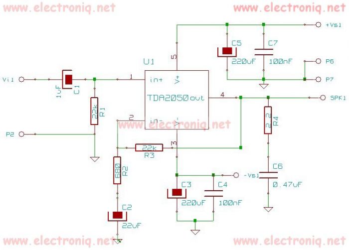
The TDA2050 integrated circuit can be used to design a simple high-fidelity audio power amplifier, intended for use as a Class AB audio amplifier. Due to its high power capabilities, the TDA2050 audio power amplifier can deliver up to...
The block diagrams presented in Figure 1 indicate that the overall signal flow in this five-input mixer underwent minimal changes following modifications. Solid-state buffers were added to provide independent direct outputs for the five preamp channels. The audio signal...
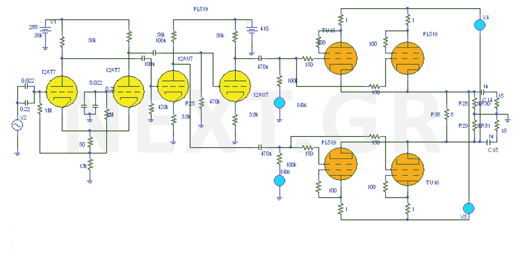
The design of the 40W Valve Amplifier is illustrated in the accompanying figure. Valve amplifiers are characterized by a prominent presence of second and third harmonics, sometimes accompanied by fourth and fifth harmonics, but always with a wider bandwidth....
For all the subsequent tests, a high-quality signal generator from BlackStar was utilized. The PicoScope trace displayed below illustrates a pure 1 kHz tone from the signal generator. It is important to note that while the screenshots below depict...

During the recent audio hackers meetup at Hacker Dojo, discussions were held with Laura and Kevin regarding the challenges faced in creating a small local network referred to as "JamLan." There was mention of the consideration to develop a...
Warning: include(partials/cookie-banner.php): Failed to open stream: Permission denied in /var/www/html/nextgr/view-circuit.php on line 713
Warning: include(): Failed opening 'partials/cookie-banner.php' for inclusion (include_path='.:/usr/share/php') in /var/www/html/nextgr/view-circuit.php on line 713