
7 segment rolling display using PC
The described circuit utilizes the 25-pin parallel port of a personal computer (PC) to control a 7-segment display. This interface is particularly advantageous for applications where visual feedback is required, such as in digital clocks, scoreboards, or any numerical display system. The parallel port operates on a range of addresses from 378H to 37AH, with the specific output pins for the display being pins 2 through 8 of the port.
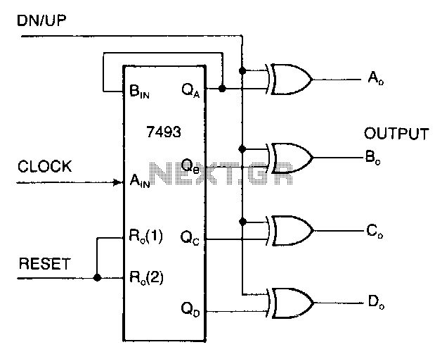
In this setup, the hardware consists of a 7-segment display, an integrated circuit (IC1), and necessary passive components such as resistors. The IC is responsible for interpreting the binary input from the parallel port and converting it into the corresponding signal to illuminate the appropriate segments of the display.
The 7-segment display itself consists of seven individual segments (labeled a through g) that can be lit in various combinations to represent decimal digits from 0 to 9. The control signals sent from the PC's printer port are in binary format, where each pin corresponds to a segment of the display. By manipulating the output pins of the parallel port, the user can control which segments are illuminated, thus displaying the desired numeral.
To facilitate communication between the PC and the display, a simple software program is required to send the correct binary values to the printer port. This program usually runs in a loop, allowing the user to change the displayed number in real-time. The use of open collector lines in the circuit allows for flexibility in connecting additional input devices, should the need arise.
Overall, this circuit exemplifies a straightforward yet effective approach to interfacing a PC with external hardware, enabling the user to control a 7-segment display through the familiar environment of a computer terminal.It is very interesting and convenient to be able to control everything while sitting at your PC terminal. Here, a simple hardware circuit and software is used to interface a 7-segment based rolling display. The printer port of a PC provides a set of points with some acting as input lines and some others as output lines.
Some lines are open collector type which can be used as input lines. The circuit given here can be used for interfacing with any type of PCs printer port. The 25-pin parallel port connector at the back of a PC is a combination of three ports. The address varies from 378H-37AH. The 7 lines of port 378H (pins 2 through 8) are used in this circuit to output the code for segment display through IC1. 🔗 External reference
Related Circuits
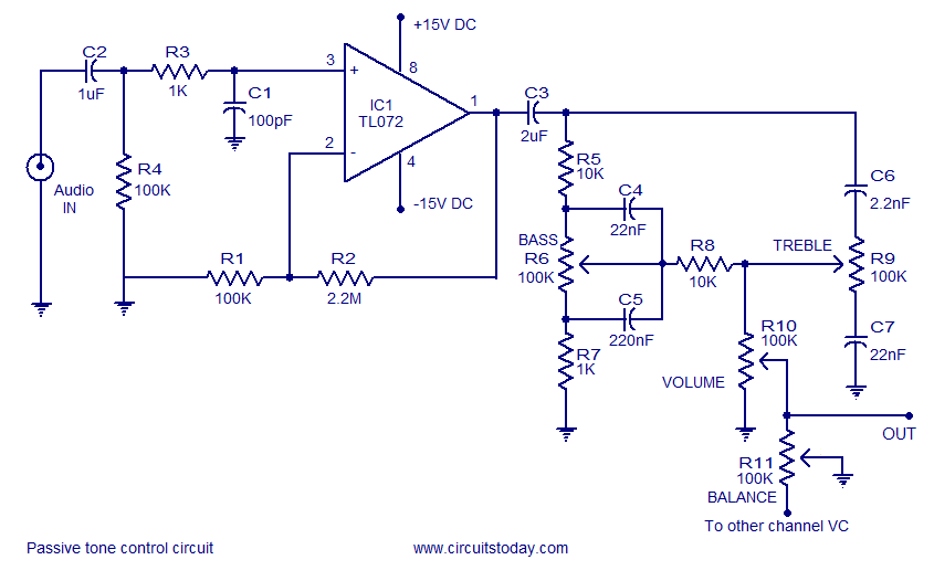
Tone control circuit utilizing an operational amplifier and a Baxandall passive tone control configuration. The overall gain is 25 dB, with a boost and cut capability of 20 dB. The circuit is powered by a dual 15V supply. The tone...
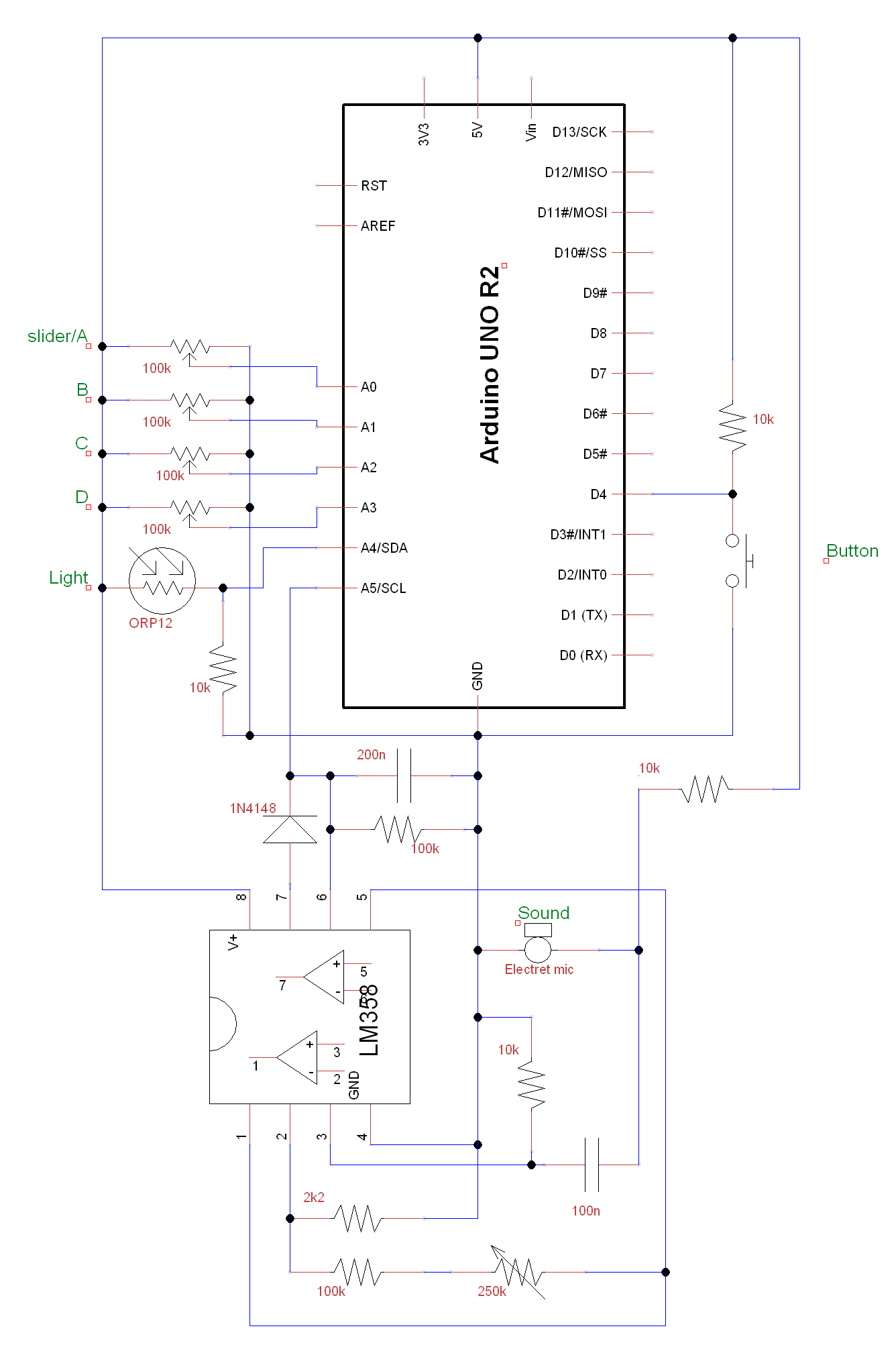
A circuit and Arduino code are designed to emulate a ScratchBoard approximately. The setup includes sound, light, a button, and four sliders, but it is not a direct replacement. It is important to change the COM ports in the...
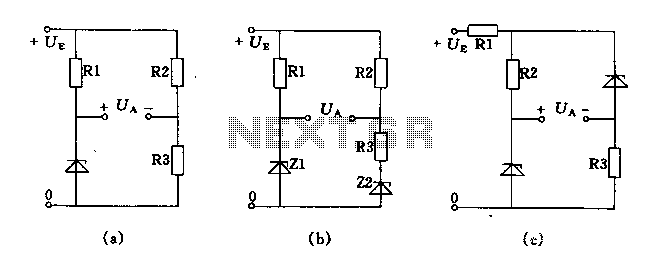
The circuit depicted in Figures A, B, and C demonstrates a high voltage coefficient. When the regulator resistance \( r_z \) is held constant, the bridge configuration achieves an infinite voltage coefficient. In Figure A, the load circuit is...
The display interface utilizes the ICM7218A/B in conjunction with an 8048 family microcontroller. An 8-bit data bus (DBO/DB7-IDO/ID7) facilitates the transfer of control and data information to the 7218 display interface during successive WRITE pulses. The mode input pins...
The documents, software, tools, and links are provided to enhance the capabilities of electronics students, hobbyists, or professionals by sharing information. This information and the associated links should be utilized by website visitors at their own risk and responsibility....
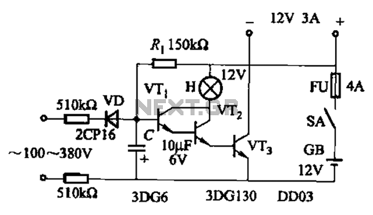
An AC-DC power supply without a power switching circuit is typically utilized for lighting load circuits. Once the power grid is restored, the standby power supply automatically switches on. An automatic switching circuit using a transistor is implemented, with...